a mobile fence

A technology of fence and driving mechanism, applied in the direction of fences, roads, building types, etc., can solve the problems of large space required for transportation and collection, waste of resources, and large volume of isolation equipment, so as to reduce traffic accident injuries, reduce resource waste, and apply wide range of effects

Active Publication Date: 2018-07-06
四川博华工程材料有限公司
View PDF7 Cites 0 Cited by
  • Summary
  • Abstract
  • Description
  • Claims
  • Application Information

AI Technical Summary

Problems solved by technology

However, there are following defects in using the above-mentioned method for fence construction: (1) The fence construction takes a long time, for example, piling and other processes are required during construction site fence, which is time-consuming and labor-intensive; The isolation equipment is bulky, and the space required for transportation and collection is huge; (3) Plastic partitions are flammable and fragile, and the probability of reuse is extremely low. Discarding them will cause environmental pollution and waste of resources

Method used


Image

  • a mobile fence
  • a mobile fence
  • a mobile fence

Examples


Embodiment 1

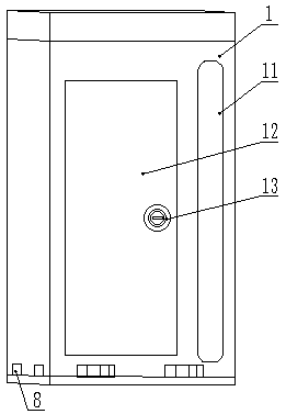
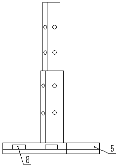
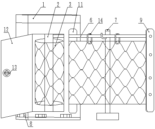
[0038] Such as Figure 1~4 Shown, a kind of motorized isolation fence, it comprises box body 1, rotating shaft 2, fence 3, main support column 5, auxiliary support column 7 and support cable 6.

[0039] Such as Figure 7 As shown, the upper and lower ends of the rotating shaft 2 are rotatably installed inside the box body 1 through bearings respectively, and the rotating shaft 2 is connected with a driving mechanism 4 for driving the rotating shaft 2 to rotate. The driving mechanism 4 is a rotating motor, and the rotating motor It is also arranged inside the box body 1. One end of the fence 3 is detachably arranged on the rotating shaft 2 , and the other end of the fence 3 can protrude from the fence outlet 11 on the box body 1 . In addition, one side of the box body 1 is also provided with a box door 12, and the box door 12 is provided with a lock body 13, and the inside of the box body 1 is provided with a locking structure, which can be locked when the fence 3 is folded. ...

Embodiment 2

[0043] The difference between this embodiment and Embodiment 1 is that: the inside of the box 1 is provided with a special support cable winding mechanism, the deployment and retraction of the support cable 6 can be controlled separately, and the box 1 is provided with a special support Cable exit 10. During use, the support cable 6 can be pulled out from the support cable outlet 10 earlier, be fixed on the main support column 5 at the far end, then expand the fence 3, be fixed on the main support column 5, and use the auxiliary support column 7 Support support cable 6, its use status is as Figure 8 shown.

Embodiment 3

[0045] The difference between this embodiment and Embodiment 2 is that: the four sides of the box body 1 are respectively provided with a support cable outlet 10 and a fence outlet 11, so that the fence 3 can be pulled out from different directions. The structure of the box body 1 is as follows: Figure 9 shown.


PUM


Abstract

The invention relates to a novel locomotive isolation fence which comprises a box body (1), a rotating shaft (2) arranged in the box body (1), a fence (3) wound to the rotating shaft (2) and support uprights, wherein the rotating shaft (2) is connected with a driving mechanism (4); the fence (3) is folded or unfolded along with the rotation of the rotating shaft (2); the box body (1) is provided with a fence outlet (11); when the fence (3) is unfolded, the support uprights are used for fixing or supporting the fence (3). The novel movable fence has the advantages of convenience in conveying, rapidness in installation, wide application range, safety, reliability, stability in installation, and the like.

Description

technical field [0001] The invention relates to the technical field of isolation equipment, in particular to a mobile fence. Background technique [0002] Isolation equipment is commonly used in building construction, road maintenance, exhibition venues, etc. Traditional isolation equipment includes plastic isolation panels for building construction, such as color steel plates; various cement piers and metal fences for temporary road maintenance , short-term use of one-meter noodles, etc. However, there are following defects in using the above-mentioned method for fence construction: (1) The fence construction takes a long time, for example, piling and other processes are required during construction site fence, which is time-consuming and labor-intensive; Isolation equipment is bulky and requires a huge space for transportation and storage; (3) Plastic partitions are flammable and fragile, and the probability of reuse is extremely low. Discarding them will cause environmen...

Claims


Application Information

Patent Timeline
Patent Type & Authority Patents(China)
IPC IPC(8): E04H17/00E01F13/02
CPCE01F13/02E01F13/028E04H17/00
Inventor 周燕燕雷新生
Owner 四川博华工程材料有限公司
Why Eureka
Try Eureka