
Electronic lock

An electronic lock and lock body technology, applied in the field of electronic locks, can solve problems such as scratches on the surface of door panels, deformation of door panel assembly holes, and inconvenient maintenance, and achieve the effect of reducing waste and damage

Inactive Publication Date: 2016-07-20
谢祥令
View PDF10 Cites 5 Cited by
  • Summary
  • Abstract
  • Description
  • Claims
  • Application Information

AI Technical Summary

Problems solved by technology

The electronic components are vulnerable and consumable parts of the electronic lock, and the panel needs to be removed for maintenance or replacement every time, which brings inconvenience to the maintenance to a considerable extent, and the repeated removal and installation of the panel will also cause deformation of the door panel assembly hole , the use of tools will also cause scratches on the surface of the door panel

Method used


Image

  • Electronic lock
  • Electronic lock
  • Electronic lock

Examples


Embodiment 1

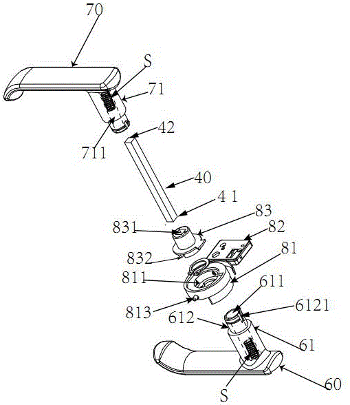
[0032] Such as figure 2 In the first embodiment shown, for the convenience of understanding, this figure only schematically shows the components involved in the present invention, and hides the conventional components of other electronic locks. In the figure, an inner handle 70 and an outer handle 60 are included. Wherein the outer handle 60 includes a joint end 61, from the end surface of the joint end 61 axially extending along the joint end 60 to form a receiving hole 611, the receiving hole 611 is almost equal to the length of the joint end 61, the receiving hole 611 A part of the outer end 41 of the connecting rod 40 can be accommodated. A reduced-diameter portion 612 is formed at the end of the coupling end 61 , and a positioning slot 6121 is formed on a side of the reduced-diameter portion 612 . Between the outer handle 60 and the inner handle 70, a clutch device 80 of an electronic lock is also provided. In this figure, the clutch device 80 is divided into a main r...

Embodiment 2

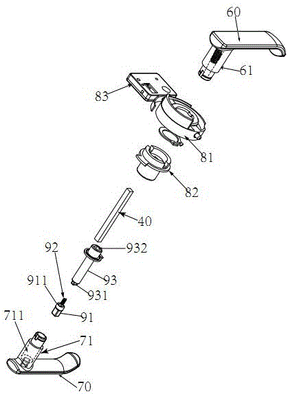
[0037] Such as image 3 As shown, the difference between embodiment two and embodiment one is only that the structure of the inner handle 70 of embodiment two, and an anti-cat's eye device 90 installed in the inner handle 70, including a button 91, a spring 92 and A transmission sleeve 93. A receiving hole 711 is provided in the middle of the inner handle 70, and the receiving hole 711 is a receiving hole with a circular cross section. There is a button hole 712 at the bottom of the receiving hole 711, the button 91 is plugged into the button hole 712, the outer end of the button 91 protrudes to the outer surface of the inner handle 70, and the button 91 has a locking part 911, which can prevent the button 91 from coming out Inner handle 70. In addition, there is a card slot (not shown) on the inner end of the button 91. After the button 91 is installed in the accommodating hole 711, the spring 92 and the transmission sleeve 93 are installed in the accommodating hole 711, wh...

Embodiment 3

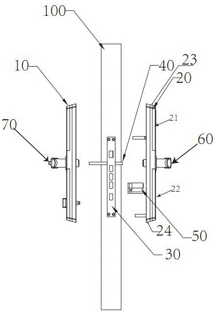
[0039] combine figure 1 and Figure 4 , Figure 5 As shown, the third embodiment is based on the second embodiment, and further describes the specific implementation structure of the outer panel 20 of the electronic lock. The outermost side of the outer panel 20, located above the outer handle 60, is a circuit board box 21 with a password button on the surface, the outer cover 22 is below the outer handle 60, the middle layer is the outer main panel 23, and the innermost layer of the outer panel 20 The side is the bottom plate 24 of the outer panel.

[0040] Such as Figure 4 Shown is an exploded view of the outer panel 20 . Wherein at least one first groove 231 and second groove 232 are formed on the outer surface of the outer main panel 23 . A circuit board box 21 is accommodated in the first groove 231 , and an outer cover 22 is covered above the second groove 232 . The circuit board box 21 is located on the upper left of the outer main panel 23, and includes an upper...


PUM


Abstract

The invention discloses an electronic lock. The electronic lock comprises a linking rod, an inner lever handle and an outer lever handle, wherein the linking rod is inserted into a lock body to act on a lock tongue; both two ends of the linking rod extend out of the lock body; the locking rod comprises an inner end and an outer end; the inner lever handle comprises a combining end; the combining end of the inner lever handle and the inner end of the linking rod form synchronous rotary combination in the rotating direction; the outer handle lever handle comprises a combining end; the combining end of the outer lever handle and the outer end of the linking rod form synchronous rotary combination or separation in the rotating direction through an engagement and disengagement device; an accommodation hole is formed in one of the combining ends of the inner lever handle and the outer lever handle or two accommodation holes are respectively formed in the two combining ends; the inner end or the outer end of the linking rod can extend into the corresponding accommodation hole, thereby adjusting the length of the linking rod between the combining end of the inner lever handle and the combining end of the outer lever handle, wherein the length is defined as an effective length; and therefore, the effective length can be adjusted by the linking rod according to the thicknesses of panel bodies of different door panels. In addition, an existing traditional lock body can be reformed into the electronic lock.

Description

technical field [0001] The invention relates to an electronic lock, in particular to an electronic lock adaptable to different thicknesses of door panels. Background technique [0002] Electronic lock is a kind of lock commonly used in the family. The electronic lock includes a sensor arranged outside the lock, and the sensor is connected with a control circuit board for signals. The sensor is a fingerprint sensor, a remote sensor or a keyboard or a mobile phone. When the sensor receives the correct unlock signal, the sensor will feed back the received signal to the control circuit board, the control circuit board will activate the clutch driver, and the clutch driver will drive the clutch, so that the clutch and the handle on the door panel form a locking position, while the clutch The other end is connected with a square bar for synchronous rotation, and the square bar is connected with a dead bolt. At this time, when the handle on the door panel is turned, the clutch, ...

Claims


Application Information

Patent Timeline
IPC IPC(8): E05B3/00E05B9/00E05B15/00E05B47/00E05B49/04E05B63/00
CPCE05B63/006E05B3/00E05B9/002E05B15/0033E05B47/0001E05B49/00E05B2047/0026E05B2047/0048
Inventor 谢祥令
Owner 谢祥令
Learn More