Rotary driving and pushing mechanism for well-drilling drill column

A technology of rotary drive and push mechanism, which is applied to the driving device for drilling in the wellbore, drilling equipment, drill pipe, etc., which can solve the problems of trouble, damage to the well body, high manufacturing cost and high use cost of the equipment

Active Publication Date: 2016-07-20
东营市虹田石油装备有限公司
View PDF7 Cites 3 Cited by
  • Summary
  • Abstract
  • Description
  • Claims
  • Application Information

AI Technical Summary

Problems solved by technology

[0002] At present, for small and medium-sized drilling, the drilling equipment is relatively complicated, resulting in very high manufacturing costs and use costs of the equipment, causing a great loss of material and financial resources
[0003] For drilling deep wells, the length of one drill pipe (drill string) cannot meet the depth requirement, which requires multiple drill pipe...

Method used


Image

  • Rotary driving and pushing mechanism for well-drilling drill column
  • Rotary driving and pushing mechanism for well-drilling drill column
  • Rotary driving and pushing mechanism for well-drilling drill column

Examples


Embodiment Construction

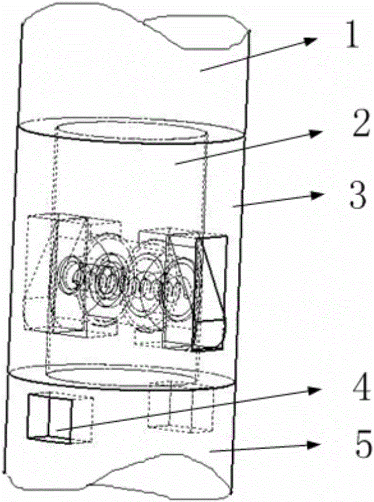
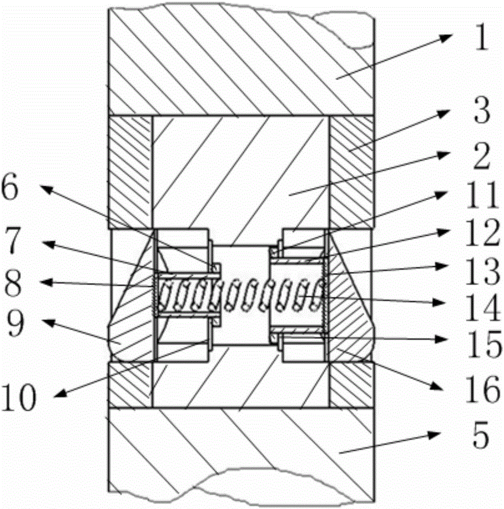
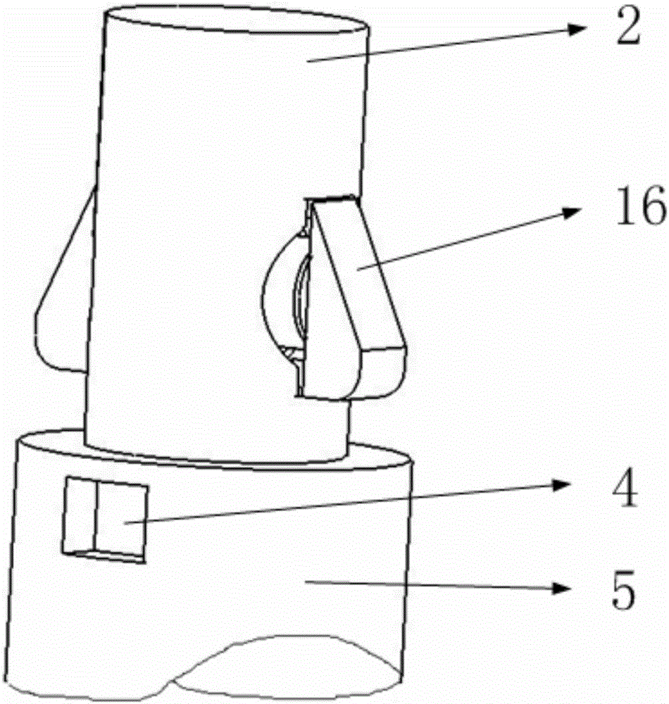
[0037] Such as Figure 11 As shown, it includes a drill pipe fixing mechanism, a driving motor, a driving motor fixing structure, a push hydraulic rod, a hollow drive shaft, a drill pipe connection structure, a hydraulic rod fixed support, and a drill pipe body. Two of the push hydraulic rods are installed in a complete manner. Similarly, for any one of them, one end of the push hydraulic rod is installed on the fixed support of the hydraulic rod fixed on the ground, and the other end of the push hydraulic rod is installed on the fixed structure of the drive motor; Figure 12 As shown, the two driving motor fixing structures are symmetrically installed on the driving motor. The rotating shaft of the driving motor is a hollow driving rotating shaft. Shorter; the above-mentioned drill pipe shafts are solid cylinders; any two drill pipe shafts are connected by a drill pipe connecting structure.

[0038] The above-mentioned two drill rod fixing mechanisms are symmetrically instal...


PUM


Abstract

The invention belongs to the technical field of well drilling and specifically relates to a rotary driving and pushing mechanism for a well-drilling drill column. The rotary driving and pushing mechanism comprises a drill rod fixing mechanism, a driving motor, a pushing hydraulic rod, a hollow driving rotary shaft, a drill rod connection structure, a hydraulic rod fixing support and drill rod bodies. The driving motor is fixed to the hydraulic rod fixing support through the pushing hydraulic rod. Stretching-out and drawing-back of the hydraulic rod can drive the driving motor to move up and down. A rotary shaft of the driving motor is the hollow driving rotary shaft. The hollow driving rotary shaft can drive the drill rod bodies to rotate and move up and down through the drill rod fixing mechanism. The two drill rod bodies are connected together through the drill rod connection structure. The designed drill rod connection structure and the drill rod fixing mechanism are organically combined, so that the connection and driving functions of the drill rod are achieved. In addition, the drill rod connection structure is compact in structure, so that the effect that the diameter of the connection position is the same as that of the drill rod bodies can be ensured, and damage to a well drilling face due to a too large drill rod connection structure is avoided. The whole mechanism has a certain practical effect.

Description

Technical field [0001] The invention belongs to the technical field of drilling, and in particular relates to a rotary driving and pushing mechanism of a drilling string. Background technique [0002] At present, for small and medium-sized drilling, the drilling equipment is relatively complicated, which results in very high manufacturing cost and use cost of the equipment, and a great loss of material and financial resources. [0003] For drilling deep wells, the length of a drill pipe (drill string) certainly cannot meet the depth requirement, which requires multiple drill pipes to be connected. At present, the external dimensions of the drill pipe connection structure used for drilling are larger than the drill pipe itself. When the drill pipe rotates to drive the drill bit to drill, the excessively large drill pipe connection structure is likely to interfere with the drilled wellbore, thereby destroying the The well has been drilled, causing unnecessary trouble. [000...

Claims


Application Information

Patent Timeline
IPC IPC(8): E21B17/046E21B17/03E21B17/00E21B4/04E21B19/086
CPCE21B4/04E21B17/00E21B17/03E21B17/046E21B19/086
Inventor 柳超
Owner 东营市虹田石油装备有限公司
Why Eureka
Try Eureka