
In-site disassembly method for rear supporting trailer when tunnel boring machine (TBM) is obliquely arranged

A post-matching and trailer technology, applied in the direction of hoisting devices, mining devices, lifting frames, etc., can solve the problems that large-scale hoisting machinery cannot be used auxiliary, in-situ dismantling has limited operable space, personnel and mechanical operations are difficult, and achieve structural Simple, easy-to-control, and easy-to-operate effects

Inactive Publication Date: 2016-07-20
CHINA RAILWAY CONSTR BRIDGE ENG BUREAU GRP
View PDF0 Cites 2 Cited by
  • Summary
  • Abstract
  • Description
  • Claims
  • Application Information

AI Technical Summary

Problems solved by technology

[0003] After the TBM descends from the surface to complete the construction of the long tunnel, the TBM needs to be dismantled and transported locally due to space constraints. Due to the large weight and volume of the TBM, the operable space for in-situ dismantling is limited, and it is difficult for personnel and machinery to operate, and large-scale hoisting The machinery cannot be used as an assistant at all, and the difficulty of the operation is manifested in the aspects of "small space, great difficulty, and high risk"

Method used


Image

  • In-site disassembly method for rear supporting trailer when tunnel boring machine (TBM) is obliquely arranged
  • In-site disassembly method for rear supporting trailer when tunnel boring machine (TBM) is obliquely arranged
  • In-site disassembly method for rear supporting trailer when tunnel boring machine (TBM) is obliquely arranged

Examples


Embodiment Construction

[0029] The features of the present invention and other related features will be further described in detail below in conjunction with the accompanying drawings through embodiments, so as to facilitate the understanding of those skilled in the art:

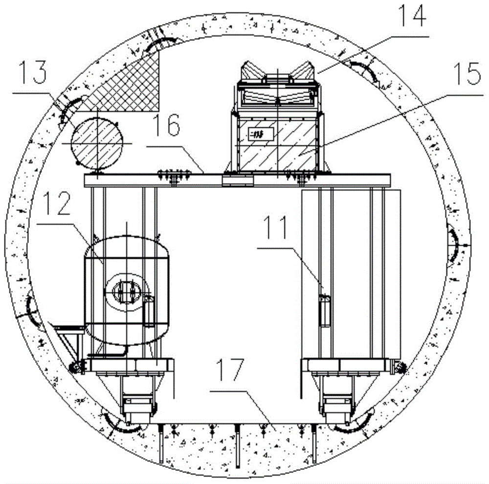
[0030] The labels in the figure are: wedge block 1, connecting plate 2, traveling wheel 3, retarding motor 4, reducer 5, tie rod 6, jacking jack 7, balance beam 8, vehicle frame 9, telescopic oil cylinder 10, right trailer Steel frame 11, left trailer steel frame 12, ventilator 13, belt conveyor 14, dust removal air duct 15, trailer connecting rod 16, tunnel invert surface 17.

[0031] A method of in-situ dismantling of the rear supporting trailer in the inclined state of the TBM is completed according to the following steps:

[0032] ① Based on the design of the supporting trailer after the TBM as a detachable structure. The trailers can not only ensure rigid connection, but also have the ability to be dismantled independently, t...


PUM


Abstract

An in-site disassembly method for a rear supporting trailer when a tunnel boring machine (TBM) is obliquely arranged comprises the following steps that (1) the TBM rear supporting trailer and a steel framework of each segment of the trailer are designed to be of detachable structures; (2) splicing type steel sleepers are arranged on the inverted arch surface and arc-shaped wall toes on the two sides of a tunnel; (3) combined lifting devices are installed on the splicing type steel sleepers; (4) the splicing type steel sleepers are placed in the position, to be jacked, of the rear supporting trailer needing to be disassembled, and then the splicing type steel sleepers are fixed; (5) a balance beam on the left side of each combined lifting device and a balance beam on the right side of each combined lifting device stretch to the position, to be jacked, of the lower portion of a bottom longitudinal beam of the trailer, and the balance beams are fixed; (6) the trailer is separated from the inverted arch surface of the tunnel by jacking; (7) the steel frames on the two sides of the trailer are moved inwards and connected in a butt joint mode; (8) the disassembled trailer is dragged and drawn out; and (9) the combined lifting devices are moved to the disassembling position of the next section of the trailer, and an operation cycle is finished. By the adoption of the method, disassembly of an in-site non-expansion underground chamber of the TBM rear supporting trailer under the limited space condition can be achieved, and no assistance of structures and large hoisting equipment is needed.

Description

technical field [0001] The invention belongs to the technical field of building construction, and in particular relates to a method for in-situ dismantling of a rear matching trailer under a TBM tilted state and a composite lifting device used therefor. The method enables the TBM to perform an in-situ non-expanded chamber in a tunnel under an inclined posture. Disassemble. Background technique [0002] At present, large-scale hard rock tunnel boring machine TBM has been widely used in transportation, hydropower and other engineering fields. With the maturity and development of TBM technology, this construction technology has begun to be applied to the construction of inclined shafts in coal mines. [0003] After the TBM descends from the surface to complete the construction of the long tunnel, the TBM needs to be dismantled and transported locally due to space constraints. Due to the large weight and volume of the TBM, the operable space for in-situ dismantling is limited, a...

Claims


Application Information

Patent Timeline
Patent Type & Authority Applications(China)
IPC IPC(8): E21F17/00B66F7/16
Inventor 毛东晖邹春华李守彪姜程华姚明会肖建军
Owner CHINA RAILWAY CONSTR BRIDGE ENG BUREAU GRP
Learn More