
Air channel structure for controlling piston rod action of eliminating air cylinder

A technology for removing cylinders and piston rods, applied in the direction of fluid pressure actuating devices, servo motors, servo motor components, etc., can solve the problems of limiting the air discharge speed, shortening the service life of the removing cylinder, and the inability of the piston rod to reset quickly. The effect of reset time

Inactive Publication Date: 2016-07-20
JIANGSU NEWAMSTAR PACKAGING MACHINERY
View PDF5 Cites 1 Cited by
  • Summary
  • Abstract
  • Description
  • Claims
  • Application Information

AI Technical Summary

Problems solved by technology

[0003] The traditional air circuit structure that controls the movement of the piston rod of the rejecting cylinder has the following defects: 1. Throttle valves are respectively set on the striking pipeline and the reset pipeline, and the units on the striking pipeline and the reset pipeline can be adjusted respectively by adjusting the throttle valves. The flow rate of compressed air within a certain period of time is used to adjust the pressure difference between the striking chamber and the reset chamber, so as to realize the adjustment of the striking speed and striking force of the piston rod. However, the setting of the throttle valve on the striking pipeline It also limits the discharge speed of the air in the impact chamber when the piston rod is reset, resulting in the piston rod not being able to reset quickly
2. When the piston rod is stretched out, the air in the reset chamber is directly exhausted from the exhaust port of the two-position five-way electromagnetic reversing valve. Under the action of the increasing air pressure in the striking chamber, the piston is easily removed. The inner wall of the cylinder produces a rigid collision, which greatly shortens the service life of the reject cylinder

Method used


Image

  • Air channel structure for controlling piston rod action of eliminating air cylinder

Examples


Embodiment Construction

[0012] The present invention will be further described in detail below in conjunction with the accompanying drawings and preferred embodiments.

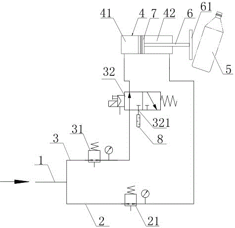
[0013] Such as figure 1 As shown, the gas path structure for controlling the movement of the piston rod of the rejecting cylinder includes: an air intake pipe 1, the inlet end of the air intake pipe 1 is connected with the compressed air source, and the outlet end of the air inlet pipe 1 is connected in parallel with the first pipeline 3 and the second pipeline. The second pipeline 2 and the first pipeline 3 are sequentially provided with a first pressure reducing valve 31 and a two-position three-way electromagnetic reversing valve 32 along the input direction of the compressed air. The two-position three-way electromagnetic reversing valve is a kind of Common automation components used to control the direction of fluid movement. The second pipeline 2 is provided with a second pressure reducing valve 21 . In this embodiment, both ...


PUM


Abstract

The invention discloses an air channel structure for controlling the piston rod action of an eliminating air cylinder. The air channel structure comprises a first pipeline and a second pipeline which are connected in parallel to the output end of an air inlet pipe; a first pressure reducing valve and a two position three-way electromagnetic valve are arranged on the first pipeline; a second pressure reducing valve is arranged on the second pipeline; the first pipeline and the second pipeline are respectively communicated with an impact cavity and a reset cavity in the eliminating air cylinder; when an unqualified bottle needs to be eliminated, compressed air enters the impact cavity and the reset cavity through the first pipeline and the second pipeline, and the pressure of air in the impact cavity is increased, so that a piston rod is driven to extend out and knock down the unqualified bottle; and then, compressed air only enters the reset cavity through the second pipeline, air in the impact cavity is exhausted from the air outlet of the two position three-way electromagnetic valve, and the pressure of air in the reset cavity is constantly increased, so that the piston rod is driven to retract inwards and reset. The air channel structure provided by the invention has the advantages that the impact velocity and strength of the eliminating air cylinder can be flexibly controlled, and the piston rod of the eliminating air cylinder can reset rapidly.

Description

technical field [0001] The invention relates to the technical field of beverage packaging production equipment, in particular to a rejecting cylinder in a packaging production line. Background technique [0002] In the production process of beverage packaging, unqualified bottles such as inaccurate liquid levels and wrong labels need to be separated from the bottle flow. The device that separates unqualified bottles in the beverage packaging production line is the rejection cylinder. A striking block is installed on the head of the piston rod of the rejecting cylinder, and the piston rod of the rejecting cylinder stretches out until the striking block knocks down the unqualified bottle and makes it fall from the bottle flow, and then the piston rod of the rejecting cylinder is reset , so that removing the cylinder will complete the removing task once. The traditional gas path structure for controlling the movement of the piston rod of the single-intake type rejecting cylin...

Claims


Application Information

Patent Timeline
IPC IPC(8): F15B11/08F15B13/02
CPCF15B11/08F15B13/02F15B13/025
Inventor 裔敏高超张迎龙
Owner JIANGSU NEWAMSTAR PACKAGING MACHINERY
Learn More