Boiler grate

A grate and boiler technology, applied in the direction of grate, rotary grate, oscillating grate, etc., can solve the problems of high smoke and dust concentration, large smoke blackness, environmental pollution, etc., achieve good ventilation effect, Good combustion effect and good slag removal effect

Inactive Publication Date: 2016-07-20
TIANJIN CITY BAODI DISTRICT KUNYU CORNCOB CO LTD
View PDF0 Cites 1 Cited by
  • Summary
  • Abstract
  • Description
  • Claims
  • Application Information

AI Technical Summary

Problems solved by technology

[0004] Using coal as fuel not only emits high smoke and dust concentration and blackness of the smoke, which causes serious pollution to the environment, but also leads to higher and higher production costs with the decreasing coal resources; in my country, there are extensive sugarcane plantations The bagasse after the sugar is squeezed can be used as fuel for boilers, but because the bagasse itself carries the sediment when it is taken back from the ground, it will block the boiler grate holes when burned, and the gas will be blocked if the grate holes are blocked. The pressure in the boiler will increase, which will eventually lead to the explosion of the boiler. Therefore, how to transform the boiler row, that is, how to rationally use the bagasse of natural resources as the fuel of the boiler, and improve the economy and reliability of the boiler is an urgent problem to be solved. a new topic
[0005] Fire grates, that is, fire grates, are needed in boiler equipment. The existing fire grates are composed of strips or ribs fixed on the overall frame. If a single strip or rib is damaged, the entire fire grate needs to be replaced, which wastes raw materials. ; and the existing grate material is mostly cast iron, which is not resistant to high temperature, and is easy to be melted and damaged when the temperature is too high, and the service life is short

Method used


Image

  • Boiler grate
  • Boiler grate

Examples


Embodiment Construction

[0016] The following will clearly and completely describe the technical solutions in the embodiments of the present invention with reference to the accompanying drawings in the embodiments of the present invention. Obviously, the described embodiments are only some, not all, embodiments of the present invention. Based on the embodiments of the present invention, all other embodiments obtained by persons of ordinary skill in the art without making creative efforts belong to the protection scope of the present invention.

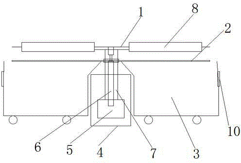
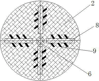
[0017] The present invention provides such figure 1 and figure 2 A boiler grate shown includes a grate 1, a grate 2 located directly below the grate 1, a slag discharge vehicle 3 located directly below the grate 2, and a support plate 4; a motor is fixed inside the support plate 4 (5), the motor 5 is provided with a rotating shaft 6, the rotating shaft 6 passes through the central position of the fire grate 1 and the fire grate 2, the rotating shaft 6 is fix...


PUM


Abstract

The invention discloses a boiler grate. The boiler grate comprises a grate, a fire bar, a slag discharge car and a support disc, wherein the fire bar is positioned under the grate, and the slag discharge car and the support disc are positioned under the fire bar; a motor is fixed to the interior of the support disc, a rotating shaft is arranged on the motor, the rotating shaft passes through the center of the grate and the fire bar and is fixedly connected with the grate, the rotating shaft is in gear connection with the fire bar, an insulation sleeve sleeves the periphery of the rotating shaft, the grate is composed of four grate segments, and strip-shaped irons are uniformly fixed to the surfaces of the grate segments. According to the boiler grate, both the grate and the fire bar can rotate around the rotating shaft, so that coal can fully burn in a burning process; the strip-shaped irons are arranged on the grate segments, so that large coal can be stirred into pieces by the strip-shaped irons in a rotating process, and the coal fully burns; slags generated by burning can fall into the slag discharge car, so that the pollution is effectively reduced, and the ventilation effect is good; the insulation sleeve fixedly sleeves the outer layer of the rotating shaft of the motor, so that the motor can be effectively protected.

Description

technical field [0001] The invention belongs to the field of boiler production, and in particular relates to a boiler grate. Background technique [0002] The boiler is a kind of energy conversion equipment; the fuel with heat energy is input into the boiler, converted by the boiler, and output to the outside [0003] Steam, high-temperature water or organic heat carrier with certain heat energy are used for people's production and living needs. Its fuel is mainly coal, [0004] Using coal as fuel not only emits high smoke and dust concentration and blackness of the smoke, which causes serious pollution to the environment, but also leads to higher and higher production costs with the decreasing coal resources; in my country, there are extensive sugarcane plantations The bagasse after the sugar is squeezed can be used as fuel for boilers, but because the bagasse itself carries the sediment when it is taken back from the ground, it will block the boiler grate holes when burne...

Claims


Application Information

Patent Timeline
Patent Type & Authority Applications(China)
IPC IPC(8): F23H9/00F23J1/00
Inventor 武定坤
Owner TIANJIN CITY BAODI DISTRICT KUNYU CORNCOB CO LTD
Why Eureka
Try Eureka