Heat energy area heating control system and method

A district heating and control system technology, applied in heating systems, hot water central heating systems, heating fuels, etc., can solve the problems of low efficiency, unsatisfactory control logic and other problems in the heating system, and achieve heating efficiency The effect of improving and improving operating efficiency

Inactive Publication Date: 2016-07-20
范旭强
View PDF6 Cites 7 Cited by
  • Summary
  • Abstract
  • Description
  • Claims
  • Application Information

AI Technical Summary

Problems solved by technology

[0002] Ordinary boilers have low efficiency and high emissions of nitrogen oxides, which cannot meet the existing national emission standards. The controller operation is complicated and the control logic is solidified, which cannot meet the real needs of various projects. The platform is flashy and cannot automatically collect and obtain effective heating data in real time. , The data entered manually in the background also lacks analysis and comparison functions. The platform only has the display function and does not have the functions of order issuance and macro-control. It lacks practical application value, and the heating data lacks targeted summary, summary, Comparative analysis
In the current heating industry, heat sources, auxiliary equipment, controllers, platforms, and management methods are all in an independent state, without overall interaction and linkage functions, and there is no data support for equipment operation, and it is all operated by manual experience. The deviation is large, the low operating efficiency of individual equipment leads to extremely low efficiency of the overall heating system, the thermal strategy is not targeted, and cannot be adjusted in real time according to the actual building heat load demand, and the user's indoor temperature is not monitored to ensure that the heating quality is up to standard
Blindly saving energy on this basis is unfounded and unscientific. The low professional level and high mobility of the boiler staff lead to high labor costs for heating companies.

Method used


Image

  • Heat energy area heating control system and method

Examples


Embodiment Construction

[0026] The present invention will be described in detail below in conjunction with the accompanying drawings and specific embodiments, wherein the schematic embodiments and descriptions are only used to explain the present invention, but are not intended to limit the present invention.

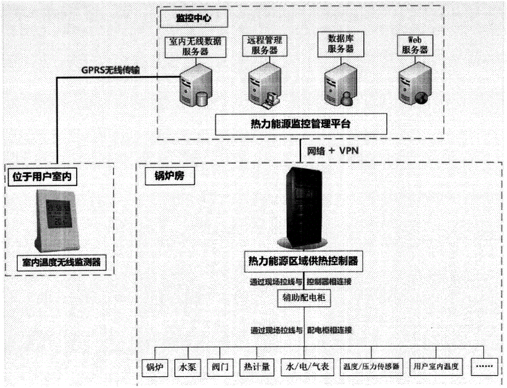
[0027] Such as figure 1 As shown, a thermal energy district heating control system includes hardware equipment and software equipment. The hardware equipment includes gas boilers, auxiliary power distribution cabinets, thermal energy district heating controllers and indoor temperature wireless monitors. The software equipment includes thermal energy Monitoring and management platform;

[0028] in,

[0029] The gas boiler provides heat for the overall system;

[0030] The thermal energy monitoring and management platform summarizes the building information and calculates the real-time heating load demand of the building. The background horizontally / vertically compares the management experienc...


PUM


Abstract

The invention relates to a heat energy area heating control system and method. The system comprises hardware equipment and software equipment. The hardware equipment comprises a gas-fired boiler, an auxiliary power distribution cabinet, a heat energy area heating controller and an indoor temperature wireless monitor. The software equipment comprises a heat energy monitoring and management platform. The heat energy area heating control system is easy to operate and reasonable in design. By the adoption of the heat energy area heating controller, all devices in a boiler room can be monitored and controlled in real time, real-time data of all the devices are collected, and the data are displayed and recorded. The heat energy area heating controller can regulate and control the devices automatically according to instructions of the upper-layer heat energy monitoring and management platform, furnace firemen can manually operate any device through the heat energy area heating controller when necessary, and therefore the operating efficiency of single device bodies and the entire heating system can be improved.

Description

【Technical field】 [0001] The invention relates to a thermal energy district heating control system and a method thereof, belonging to the technical field of intelligent heating. 【Background technique】 [0002] Ordinary boilers have low efficiency and high emissions of nitrogen oxides, which cannot meet the existing national emission standards. The controller operation is complicated and the control logic is solidified, which cannot meet the real needs of various projects. The platform is flashy and cannot automatically collect and obtain effective heating data in real time. , The data entered manually in the background also lacks analysis and comparison functions. The platform only has the display function and does not have the functions of order issuance and macro-control. It lacks practical application value, and the heating data lacks targeted summary, summary, Comparative analysis. In the current heating industry, heat sources, auxiliary equipment, controllers, platform...

Claims


Application Information

Patent Timeline
Patent Type & Authority Applications(China)
IPC IPC(8): F24D3/00F24D19/10
CPCF24D3/00F24D19/10F24D19/1009F24D2200/04
Inventor 范旭强
Owner 范旭强
Why Eureka
Try Eureka