
On-line monitoring and verification device for distributed capacitive equipment and on-site verification method based on the device

A technology of capacitive equipment and calibration devices, applied in the direction of measuring devices, measuring electrical variables, instruments, etc., can solve the problem of large disassembly workload that is not suitable for the development of calibration work of on-line monitoring devices, leakage current sampling units and reference voltage sampling Units are far apart, reference voltage and reference current cannot be provided, etc., to reduce equipment risks and personal safety risks, improve on-site calibration accuracy, and reduce workload

Inactive Publication Date: 2019-03-15
福建和盛高科技产业有限公司
View PDF4 Cites 0 Cited by
  • Summary
  • Abstract
  • Description
  • Claims
  • Application Information

AI Technical Summary

Problems solved by technology

[0003] a) At present, the online monitoring device uses a distributed scheme. Since the leakage current sampling unit and the reference voltage sampling unit are far apart, the existing on-site verification device of the online monitoring system cannot provide the reference voltage and reference current for the system at the same time
[0004] b) The small current current transformer used in the online monitoring device is connected in series to the grounding wire of the last screen, and its disassembly requires a lot of work, which is not suitable for the calibration work of the online monitoring device
Moreover, there are greater equipment risks and personal safety risks in live disconnection and bypass ground wires
[0005] c) The zero-flux current transformer used in the online monitoring device is connected in series to the grounding wire of the last screen, and the workload of disassembly is large during the calibration, which is not suitable for the calibration of the online monitoring device.

Method used


Image

  • On-line monitoring and verification device for distributed capacitive equipment and on-site verification method based on the device
  • On-line monitoring and verification device for distributed capacitive equipment and on-site verification method based on the device

Examples


Embodiment 1

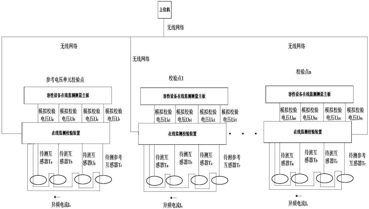
[0055] Such as figure 1 As shown, this embodiment is an online monitoring and verification device for distributed capacitive equipment, which is characterized in that it includes:

[0056] The processor is used to control the operation of the radio frequency transceiver, storage circuit, analog-to-digital converter and digital-to-analog converter, and can analyze and process data;

[0057] The radio frequency transceiver is connected with the processor for communication with the host computer and timing;

[0058] The storage circuit is connected with the processor and is used for storing and processing and analyzing the data collected by the analog-to-digital converter;

[0059] An analog-to-digital converter, connected to the processor, is used to convert the collected analog signal into a digital signal for analysis and processing;

[0060] A digital-to-analog converter, connected to the processor, is used to convert digital signals into analog signals to generate power freq...

Embodiment 2

[0071] Such as figure 2 As shown, this embodiment is an on-site verification method of a distributed capacitive equipment online monitoring and verification device. The method uses a distributed capacitive equipment online monitoring and verification device. This verification method includes a small current transformer calibration The verification part and the measurement board verification part include the following steps:

[0072] Step 1: Connect the distributed capacitive equipment online monitoring and verification device to the capacitive equipment online monitoring device;

[0073] Small current transformer calibration part:

[0074] Step 2: Using the distributed capacitive equipment online monitoring and verification device to obtain the error data of the small current transformer of the capacitive equipment online monitoring device;

[0075] Further, the step 2 is further specifically: the distributed capacitive equipment online monitoring and verification device ge...


PUM


Abstract

The present invention relates to the field of power equipment online monitoring and specifically relates to a distributed capacitive equipment online monitoring and calibration device and a field calibration method based on the device. The device comprises a processor, an RF transceiver, a memory circuit, an analog to digital converter, a digital to analog converter, an input channel conditioning circuit, a conditioning circuit I, and a conditioning circuit II. The calibration method comprises the steps of (1) connecting the distributed capacitive equipment online monitoring and calibration device into a capacitive equipment online monitoring device, (2) obtaining the error data of a small current transformer, (3) generating a group of analog signals and loading the analog signals to a measurement motherboard so as to obtain the error data of the measurement motherboard, (4) carrying out error fitting on the error data of the small current transformer and the measurement motherboard and thus judging the reliability of the capacitive equipment online monitoring device. According to the invention, the field calibration accuracy and reliability of the capacitive equipment online monitoring device can be improved, the operation steps of field calibration are simplified, and the operation is safe.

Description

technical field [0001] The invention relates to the field of on-line monitoring of electric power equipment, in particular to an on-line monitoring and verification device for distributed capacitive equipment and an on-site verification method based on the device. Background technique [0002] At present, the online monitoring technology of capacitive equipment has been widely used in 220kV and above voltage level substations. The long-term operation shows that the online monitoring technology can effectively provide early warning for the failure of capacitive equipment. However, with the aging of the online monitoring device, the monitoring accuracy It will gradually decrease and often cause false alarms, so it is necessary to check the installed online monitoring devices. The on-site verification of online monitoring devices currently has the following problems: [0003] a) The current online monitoring device uses a distributed scheme. Since the leakage current sampling ...

Claims


Application Information

Patent Timeline
Patent Type & Authority Patents(China)
IPC IPC(8): G01R35/00
CPCG01R35/005
Inventor 廉彦超陈敏维张少涵雷龙武曹立波黄永冰陈珂
Owner 福建和盛高科技产业有限公司
Learn More