Optical beam splitting device having adjustable splitting ratio

A technology of optical beam splitter and splitting ratio, which is applied in optics, instruments, optical components, etc., and can solve problems such as large polarization-related losses and limited use of large areas

Inactive Publication Date: 2016-07-20
韩朝阳
View PDF6 Cites 0 Cited by
  • Summary
  • Abstract
  • Description
  • Claims
  • Application Information

AI Technical Summary

Problems solved by technology

However, this method often brings large polarization-dependent losses, which limits its large-area use in the communication field.

Method used


Image

  • Optical beam splitting device having adjustable splitting ratio
  • Optical beam splitting device having adjustable splitting ratio

Examples


Embodiment Construction

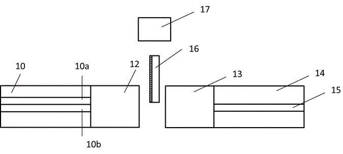
[0009] Such as figure 1 The optical beam splitter with adjustable splitting ratio shown includes: a double optical fiber head (10) for inputting and outputting optical signals, a collimating lens (12), and a linearly movable optical reflector (16) , a collimating lens (13), a single optical fiber head (14) and an actuator (17) for driving the light reflector to move linearly.

[0010] The light reflector (16) includes a plane coated with a total reflection film on one side. In order to reduce the impact of mechanical size and environment, the optical reflector (16) is preferably located on the focal plane of the collimating lens (12) and performs linear movement in or out along the focal plane. The light reflector (16) enters or moves out of the optical path is driven by the actuator (17).

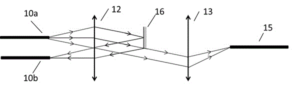
[0011] Such as figure 2 As shown in the schematic diagram of the optical path, the input optical signal from the input port (10a) is collimated by the collimator lens (12), and part of...


PUM


Abstract

The invention provides an optical beam splitting device having an adjustable splitting ratio. The optical beam splitting device comprises a double-optical fiber head having an input function and an output function, an optical reflector capable of moving linearly, a collimating lens used for the double-optical fiber head, a single-optical fiber head used for receiving, a collimating lens used for the single-optical fiber head, and an actuator used for driving the optical reflector to move linearly. The adjusting of the splitting ratio can be realized by changing the position of the movable optical reflector in the optical path. The optical beam splitting device has advantages of simple structure, easy production, applicability in large-scale production, and abilities of realizing dynamic adjusting of large-scale splitting ratio and realizing miniaturization.

Description

technical field [0001] The present invention relates to the dynamic distribution of optical power between optical elements; more particularly, to providing an optical beam splitter with adjustable splitting ratio. Background technique [0002] With the intelligentization of communication networks and the extensive use of high-power semiconductor lasers / fiber amplifiers, how to dynamically allocate optical power to transmission lines becomes more important. [0003] Common optical beam splitters with adjustable splitting ratio mainly use space or waveguide. The spatial beam splitter is mainly based on the principle of reflection / transmission. For example, Chinese patent CN101216606B achieves beam splitting by moving the transmittance gradient coating sheet, and the beam splitting ratio changes monotonously along its length. In the implementation of this solution, the requirements for the gradient coating film with transmittance are high; at the same time, the length of the f...

Claims


Application Information

Patent Timeline
Patent Type & Authority Applications(China)
IPC IPC(8): G02B27/10
Inventor 韩朝阳
Owner 韩朝阳
Why Eureka
Try Eureka