Retention spectroscopic device and method

A spectroscopic device and spectroscopic technology, applied in the direction of light guides, optics, optical components, etc., can solve the problems of high processing cost, limited spectroscopic range, high failure rate, etc., and achieve the effect of low cost and reduced propagation loss

Active Publication Date: 2018-06-26
INST OF HIGH ENERGY PHYSICS CHINESE ACAD OF SCI
View PDF4 Cites 0 Cited by
  • Summary
  • Abstract
  • Description
  • Claims
  • Application Information

AI Technical Summary

Problems solved by technology

[0007] The first is that the range of light splitting is limited. Generally, fiber fusion technology can only achieve a splitting ratio of less than 1:10. Although the splitting mirror technology can achieve a higher ratio of splitting light, the effect is not ideal, and when the splitting ratio exceeds 1:90 After the range, nothing can be done
[0008] The second is that the technology is very difficult to realize. Whether it is fiber fusion technology or spectroscopic mirror coating technology, to achieve a relatively large proportion of light splitting effect, the corresponding technical processing will be very difficult and the failure rate will be relatively high.
[0009] The third is the high processing cost. The market price of a 1:90 ratio beam splitter is more than 700 yuan, and the cost of a bifurcated optical fiber splitting structure made by optical fiber fusion technology is also more than 100 yuan.

Method used


Image

  • Retention spectroscopic device and method
  • Retention spectroscopic device and method
  • Retention spectroscopic device and method

Examples


Embodiment Construction

[0033] The application will be further described in detail below in conjunction with the accompanying drawings and embodiments. It should be understood that the specific embodiments described here are only used to explain related inventions, rather than to limit the invention. It should also be noted that, for ease of description, only parts related to the invention are shown in the drawings.

[0034] It should be noted that, in the case of no conflict, the embodiments in the present application and the features in the embodiments can be combined with each other. The present application will be described in detail below with reference to the accompanying drawings and embodiments.

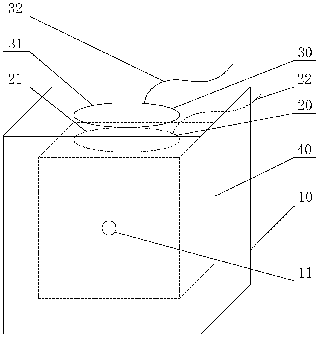
[0035] figure 1 It is a schematic structural diagram of a residence-type spectroscopic device provided by an embodiment of the present invention.

[0036] Such as figure 1 As shown, in this embodiment, the retention type spectroscopic device provided by the present invention includes a reflectiv...


PUM


Abstract

The invention discloses a retention-type light splitting apparatus and a method. The apparatus comprises a reflective film cavity, a first output light guide and a second output light guide. The reflective film cavity is used for separating light signals irradiating an inner wall of the cavity so as to acquire a first light signal which is propagated in the reflective film cavity after reflection and a second light signal which is propagated outside the reflective film cavity after transmission. The first output light guide is arranged in the reflective film cavity and is used for collecting and outputting the first light signal irradiating to the first output light guide. The second output light guide is arranged on an external surface of the reflective film cavity and is used for collecting and outputting the second light signal irradiating to the second output light guide. The reflective film cavity with a high reflectivity is arranged to separate the light signals so as to acquire the reflected first light signal and the transmitted second light signal; the output light guides are arranged respectively so as to carry out acquisition and output so that a high splitting ratio is realized; and further through changing a light guide area, the splitting ratio is adjusted.

Description

technical field [0001] The present application relates to the technical field of light intensity distribution, in particular to a retention type spectroscopic device and method. Background technique [0002] According to different wavelengths, electromagnetic waves can be divided into X-rays, ultraviolet rays, visible light, infrared rays, radio waves, etc. Visible light refers to electromagnetic waves with a wavelength ranging from 400nm to 760nm. Visible light can be directly recognized by the naked eye without the aid of instruments. Light can be regarded as photons or photons. Light intensity refers to the number of photons. Spectroscopy is the technology of dividing photons of a beam of light into two parts of equal or unequal ratio. [0003] For visible light, there are two common spectroscopic methods: [0004] The first method is to use fiber fusion, that is, use heating to fuse the ends of two optical fibers together to form a "Y"-shaped bifurcated structure. Wh...

Claims


Application Information

Patent Timeline
Patent Type & Authority Patents(China)
IPC IPC(8): G02B6/00
CPCG02B6/0055G02B6/0063
Inventor 张力刘鑫董永伟王瑞杰王志刚
Owner INST OF HIGH ENERGY PHYSICS CHINESE ACAD OF SCI
Why Eureka
Try Eureka