A photoelectric optical repeater, a long-distance box, and a processing method for uplink and downlink optical signals

An optical repeater and optical signal technology, which is applied in the field of optical access, can solve problems such as difficult implementation and complex repeater structure, and achieve the effects of easier implementation, increased splitting ratio, and extended transmission distance

Active Publication Date: 2017-07-11
徐州核润光能有限公司
View PDF5 Cites 0 Cited by
  • Summary
  • Abstract
  • Description
  • Claims
  • Application Information

AI Technical Summary

Problems solved by technology

[0011] The embodiment of the present invention provides a photoelectric optical repeater, which is used to solve the problem that the structure of the repeater in the prior art is complex and difficult to implement

Method used


Image

  • A photoelectric optical repeater, a long-distance box, and a processing method for uplink and downlink optical signals
  • A photoelectric optical repeater, a long-distance box, and a processing method for uplink and downlink optical signals
  • A photoelectric optical repeater, a long-distance box, and a processing method for uplink and downlink optical signals

Examples


Embodiment 1

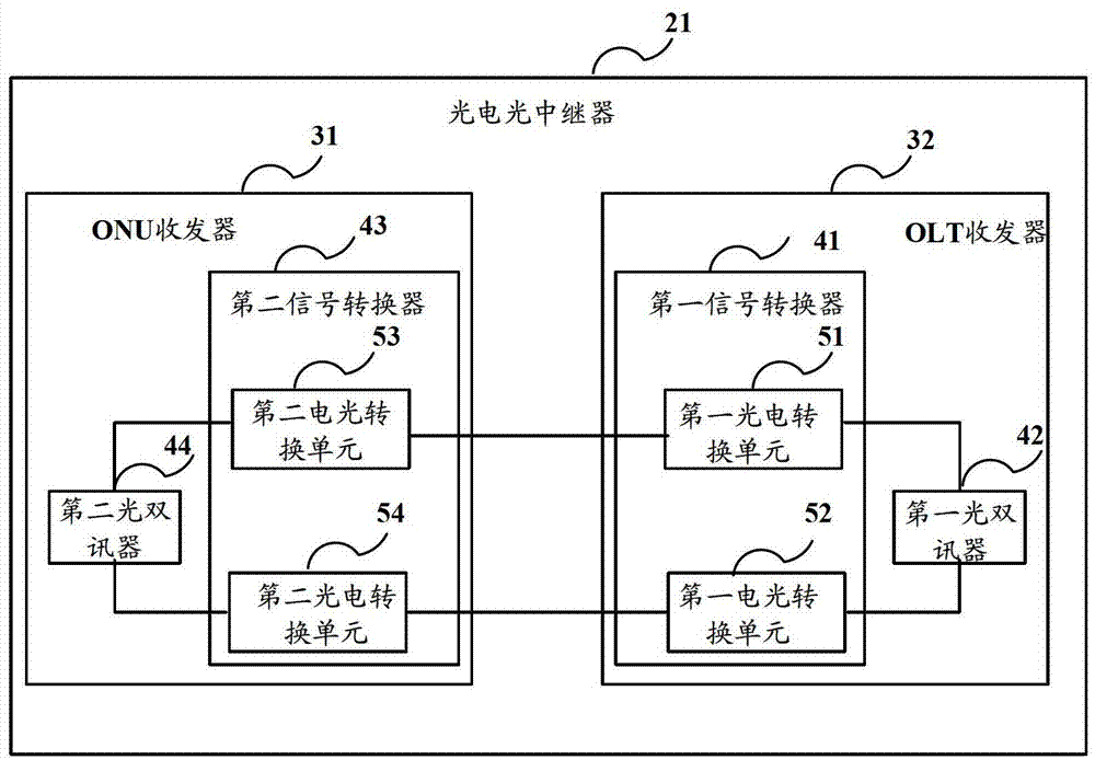
[0068] like image 3 As shown, it is a schematic structural diagram of an optoelectronic optical repeater 21 in Embodiment 1 of the present invention, and the optoelectronic optical repeater 21 includes: an ONU transceiver 31 and an OLT transceiver 32 .

[0069] The ONU transceiver 31 is used to perform photoelectric conversion and re-amplification and re-shaping on the received downlink optical signal, and output the down-link electrical signal obtained after the conversion, re-amplification and re-shaping to the OLT transceiver 32, and to the OLT from the OLT. performing electrical-optical conversion on the uplink electrical signal of the transceiver 32, and outputting the converted uplink optical signal;

[0070] When the photoelectric optical repeater repeater is applied in TDM-PON, the downlink optical signal that ONU transceiver 31 receives can be from the OLT in this TDM-PON; At this moment, ONU transceiver 31 can convert The obtained uplink optical signal is then outp...

Embodiment 2

[0101] Considering that the ONU transceiver 31 in the optoelectronic optical repeater 21 needs to turn off its transmitting switch when not transmitting the upstream optical signal, stop the operation on the upstream optical signal, so as to avoid crosstalk of other optical signals and ensure The normal operation of the repeater; and when the ONU transceiver 32 finishes receiving the upstream optical signal this time, it will keep the reset state in time, so as to process the upstream optical signal input into it next time. Embodiment 2 of the present invention is based on Embodiment 1 On the basis of the above, the structure of the photoelectric optical repeater is further optimized, and its schematic diagram is shown in Figure 7 shown.

[0102] The photoelectric optical repeater 21 also includes: a logic unit 33;

[0103] The OLT transceiver 32 is further configured to output a detection signal to the logic unit, and the detection signal is output by the OLT transceiver ac...

Embodiment 3

[0125] like Figure 9 As shown, it is a schematic structural diagram of the long-distance box in Embodiment 3 of the present invention, and the long-distance box includes: an optoelectronic optical repeater 21 and a 1:4 coupler 22 .

[0126] The photoelectric optical repeater 21 is used to reshape and re-amplify the downlink optical signal from the OLT and output it to the 1:4 coupler, and reshape and re-amplify the uplink optical signal from the 1:4 coupler Then output to OLT;

[0127] The 1: N coupler 22 is used to divide the downlink optical signal output by the photoelectric optical repeater into 4 paths, and output them to the 4 optical splitters connected to itself, and each optical splitter to be connected to itself The output uplink optical signal is coupled into one channel and then output to the optoelectronic optical repeater 21 .

[0128] Preferably, in order to reduce the insertion loss of the uplink optical signal passing through the 1:4 coupler, the photoelect...


PUM


Abstract

The invention discloses a photoelectric optical repeater, a long-distance box and a processing method for uplink and downlink optical signals. Amplify and output the reshaped and amplified downlink optical signal to the 1:N coupler in the long-distance box. The 1:N coupler divides the received downlink optical signal into N channels of downlink optical signals and outputs them to the connected an optical splitter, and combine the uplink optical signals of each optical splitter into one channel. On the one hand, the photoelectric optical repeater in the long-distance box re-shapes and re-amplifies the uplink and downlink signals respectively, and outputs the reshaped and amplified downlink optical signal, which prolongs the transmission distance of the optical signal; on the other hand, The insertion loss of the 1:N coupler in the long-distance box is small, which makes it possible to increase the splitting ratio in the PON. Therefore, the long-distance box in the present invention increases the The splitting ratio in PON is improved.

Description

technical field [0001] The invention relates to the field of optical access technology, in particular to a photoelectric optical repeater, a long-distance box and a processing method for uplink and downlink optical signals. Background technique [0002] In the context of global informatization, broadband access is developing rapidly. The fiber-to-the-x (FTTx) construction model has greatly reduced the construction cost of broadband access networks, and realized the bandwidth increase of the access network at a lower cost. The development of FTTx has added a strong momentum. [0003] With the advancement of FTTx network construction, operators are eager to reduce the cost of FTTx network construction and operation and maintenance. Large capacity and fewer offices are the development direction of future access networks. [0004] Passive Optical Network (PON) technology is a point-to-multipoint optical fiber access technology. Commonly used time division multiplexing passive...

Claims


Application Information

Patent Timeline
Patent Type & Authority Patents(China)
IPC IPC(8): H04B10/297H04B10/299
Inventor 张锡芳付志明徐继东刘欣张德智
Owner 徐州核润光能有限公司
Why Eureka
Try Eureka