A balanced phase-locked loop system and method for phase-locking and data separation

A technology of data separation and phase-locked loop, applied in automatic control of power, optical fiber transmission, electrical components, etc., can solve the problems of DC coupling required for photoelectric reception, easily damaged microwave amplifiers, and affecting receiver sensitivity, etc., to achieve reduction Difficulty, flexible modulation, and increased closed-loop stability

Active Publication Date: 2017-09-29
XIAN INSTITUE OF SPACE RADIO TECH
View PDF3 Cites 0 Cited by
  • Summary
  • Abstract
  • Description
  • Claims
  • Application Information

AI Technical Summary

Problems solved by technology

Among them, the balanced phase-locked loop and the jitter phase-locked loop use a 180° optical mixer, and the structure is relatively simple; the Costas phase-locked loop and the decision-making phase-locked loop need to use a 90° optical mixer, which is complex and difficult to manufacture
The structure of the balanced phase-locked loop is the simplest, but there are two deficiencies: on the one hand, the residual carrier information of the modulated signal is required, and on the other hand, the photoelectric reception requires DC coupling
Since the thermal noise of the photodetector is inversely proportional to the load resistance, the output noise of the DC-coupled amplifier using a 50 ohm load is relatively large, which affects the sensitivity of the receiver
In addition, the current 50-ohm load-matched, DC-coupled microwave broadband amplifier is not the mainstream use of microwave amplifiers due to the need for DC coupling, it is difficult to design, and it is easy to damage the microwave amplifier
Therefore, there is a need for an improved balanced phase-locked loop, which can effectively use the characteristics of optical splitting, so that phase-locking and data reception use different optical paths, so as to solve the above-mentioned DC coupling problem, and can directly use commercial transimpedance amplifiers to conduct photocurrent analysis. Amplification, its implementation complexity and receiving sensitivity are better than the classic balanced optical phase-locked loop, which cannot be solved by the existing technology

Method used


Image

  • A balanced phase-locked loop system and method for phase-locking and data separation
  • A balanced phase-locked loop system and method for phase-locking and data separation

Examples


Embodiment Construction
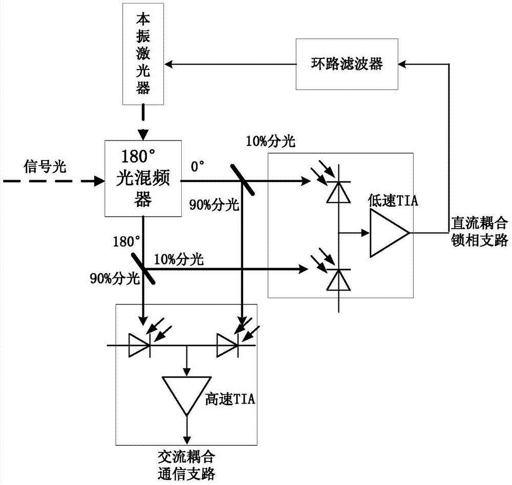
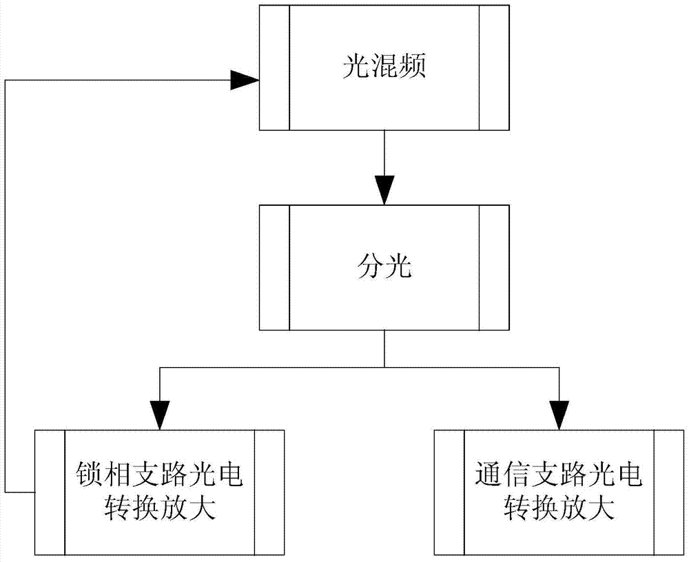
[0023] The basic idea of ​​the present invention is to provide a balanced phase-locked loop system and method for phase-locking and data separation, aiming at the shortcoming that a balanced optical phase-locked loop needs a high-speed DC-coupled amplifier, the innovation of the present invention is to use optical The splitting method separates the phase-locking and data receiving optical paths, so that phase-locking and data receiving use different detection amplifier circuits, so that the communication branch can be realized by using commercial AC-coupled transimpedance amplifiers, avoiding complex DC-coupled transimpedance amplifier and the resulting noise.

[0024] The present invention will be described in further detail below in conjunction with accompanying drawing, as figure 1 Shown is the system block diagram, a balanced phase-locked loop system with phase-locking and data separation, including: 180° optical mixer, local oscillator laser, beam splitter, balanced photo...


PUM


Abstract

The invention discloses a balanced phase-locked loop system and method for phase-locking and data separation. The invention separates the phase-locking branch and the communication receiving branch before the photoelectric detector, so that the phase-locking branch adopts low-speed DC coupling and low noise Amplifiers, high-speed AC-coupled amplifiers are used in the communication branch, thereby avoiding the use of DC-coupled high-speed broadband amplifiers. It has the advantages of flexible configuration of phase-locking and communication reception, and can directly use commercial transimpedance amplifiers, which reduces the difficulty of realizing a balanced phase-locked loop. The invention has a simple structure, can use a simple 180° optical mixer, and is suitable for optical carrier recovery in a spatial optical coherent receiver.

Description

technical field [0001] The invention relates to a phase-locked and data-separated balanced phase-locked loop system and method, which belong to the field of coherent optical communication receiving technology, space optical communication receiving technology and laser radar technology, and are mainly used in coherent optical fiber communication, atmospheric free space optical communication, Inter-satellite / satellite space optical communication and other space optical communication fields. Background technique [0002] Laser receiving technology based on coherent optical communication has broad application prospects due to its high receiving sensitivity. At present, the high-speed optical fiber communication system on the ground and the high-speed data transmission between satellites have been applied, which is a new generation of optical communication receiving and processing technology. [0003] Optical phase-locked loop technology is one of the carrier recovery methods fo...

Claims


Application Information

Patent Timeline
Patent Type & Authority Patents(China)
IPC IPC(8): H04B10/11H04B10/25H03L7/08
Inventor 郭精忠兰枫付灵丽幺周石陈祥陈安和
Owner XIAN INSTITUE OF SPACE RADIO TECH
Why Eureka
Try Eureka