Optical Line Terminal and Optical Network Unit

A technology of optical network unit and optical line terminal, which is applied in the direction of electromagnetic network arrangement, electrical components, time-division optical multiplexing system, etc., which can solve the problems of low modulation efficiency, reduced splitting ratio, and difficult problems, so as to improve transmission performance and improve Effect of splitting ratio and extended transmission distance

Active Publication Date: 2019-09-24
ALCATEL LUCENT SHANGHAI BELL CO LTD
View PDF5 Cites 0 Cited by
  • Summary
  • Abstract
  • Description
  • Claims
  • Application Information

AI Technical Summary

Problems solved by technology

And due to the low modulation efficiency of DML lasers and the pulse spreading (pulse spreading) and transmission performance loss caused by strong frequency chirp, it is difficult to directly use lower rate 2.5Gb / s DML lasers for symmetrical 40Gb / s TWDM-PON system generates 10Gb / s high-speed uplink signal
[0006] Intuitively, a 10Gb / s high-speed DML laser can be used for 10Gb / s uplink signal transmission to realize a symmetrical 40Gb / s TWDM-PON system, but the cost of a 10Gb / s DML laser is 2.5Gb / s 2 to 3 times that of DML lasers
Furthermore, 10Gb / s DML lasers are severely affected by frequency chirp
The transmission distance of the usual 10Gb / s DML laser is less than 20km, and the splitting ratio in the PON system will be greatly reduced, which will make it unable to match the requirements of NG-PON2
Since TWDM-PON has high cost requirements, low-speed 2.5Gb / s DML lasers are used to transmit 10Gb / s uplink signals on optical fibers with a length greater than 40km, so as to achieve a TWDM-PON system with a high splitting ratio. is fascinating but also challenging

Method used


Image

  • Optical Line Terminal and Optical Network Unit
  • Optical Line Terminal and Optical Network Unit
  • Optical Line Terminal and Optical Network Unit

Examples


Embodiment Construction

[0041] The basic ideas of the embodiments of the present disclosure are:

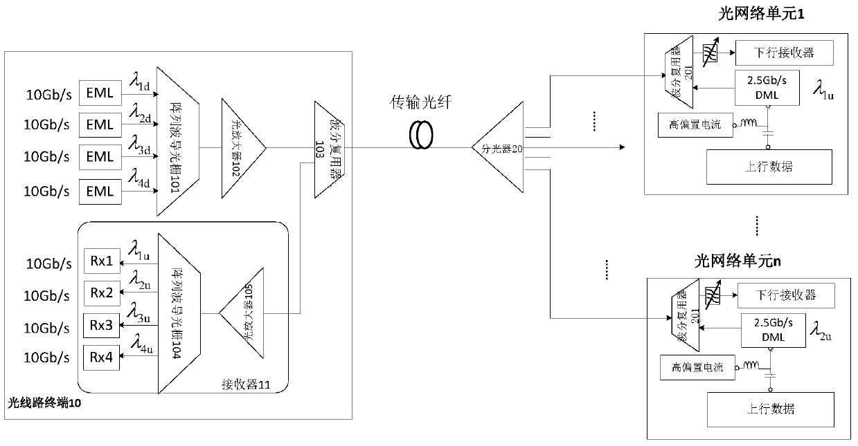
[0042] 1. Unlike the traditional high-speed transmitter used for high-speed uplink transmission, only low-speed and low-cost 2.5Gb / s DML lasers are used on the ONU transmitter side to provide 40Gb / s or above symmetrical TWDM- The PON system transmits 10 Gb / s or even above non-return-to-zero-binary on-off keying (NRZ-OOK, On-Off Keying) optical signal (ie, binary optical intensity modulation format). This will eliminate the need for any other high-speed optical components on the ONU side, thereby saving costs.

[0043] 2. In the prior art, the bias current of the DML laser is located near the threshold current of the DML laser, and the traditional DML laser is modulated with a high-amplitude current carrying data to obtain a high extinction ratio. In contrast, in the embodiments of the present disclosure, a low-speed 2.5Gb / s DML laser is driven with a higher bias current, and modulated with a relatively...


PUM


Abstract

Embodiments of the present disclosure provide an optical line terminal and an optical network unit. According to an embodiment of the present disclosure, a transmitter for an optical network unit is proposed, comprising: a 2.5Gb / s directly modulated semiconductor laser for generating an upstream optical signal; wherein the directly modulated semiconductor laser is composed of a modulation current and a The bias current is driven, the bias current is configured to be greater than the threshold current of the directly modulated semiconductor laser, and the amplitude of the modulation current is configured such that the difference between the frequency of 1 bit and the frequency of 0 bits of the upstream optical signal is the upstream optical signal half of the transfer rate. According to another embodiment of the present disclosure, a receiver for an optical line termination is presented. Here, high-speed upstream transmission of 10Gb / s data is achieved by using a low-cost and low-rate 2.5Gb / s DML laser as a transmitter, thereby achieving a long-distance 40Gb / s symmetrical TWDM‑PON. Here, no other high-speed and expensive optical transmitters need to be installed at the optical network unit.

Description

technical field [0001] Embodiments of the present disclosure relate to a Time Division Wavelength Division Multiplexing Passive Optical Network (TWDM-PON) system, and in particular to an OLT and an ONU in the TWDM-PON system. Background technique [0002] Due to its low cost and backward compatibility with traditional GPON / XGPON, TWDM-PON has been selected by ITU-T as the next generation passive optical network The main technology of network access (NG-PON2). At the initial stage, the TWDM-PON aims to provide a total of 40 Gbp / s downstream bandwidth and a total of 10 Gbp / s upstream bandwidth by multiplexing four wavelength channel pairs. Here, each wavelength pair is modulated at 2.5Gbp / s uplink and 40Gbp / s downlink. [0003] However, in order to meet future requirements for bandwidth-consuming services, future TWDM-PON needs to provide a rate of 10Gbp / s per wavelength in the uplink to achieve a symmetrical TWDM-PON of 40Gbp / s. In addition, in the ITU-TG.989.2 standard of...

Claims


Application Information

Patent Timeline
Patent Type & Authority Patents(China)
IPC IPC(8): H04Q11/00H04B10/50
CPCH04B10/503H04Q11/0067H04B10/516H04B10/504H04B10/6164H04J14/02H04B10/27H04B10/54H04J14/08
Inventor 高震森
Owner ALCATEL LUCENT SHANGHAI BELL CO LTD
Why Eureka
Try Eureka