Heat-driven electroless steam compression refrigerating device

A technology of compressing refrigeration and steam, which is applied in the field of refrigeration equipment and vapor compression refrigeration equipment. It can solve the problems of inconvenient expansion, small system, and low refrigeration efficiency, and achieve the effect of easy miniaturization, realization of miniaturization, and easy realization.

Inactive Publication Date: 2016-10-12
UNIV OF SHANGHAI FOR SCI & TECH
View PDF7 Cites 0 Cited by
  • Summary
  • Abstract
  • Description
  • Claims
  • Application Information

AI Technical Summary

Problems solved by technology

Lithium bromide refrigeration equipment is huge, not suitable for use in small places, and the system is highly corrosive; and ammonia water absorption refrigeration requires a rectifier, which makes the system complicated and poor in reliability; and these two refrigeration devices require electricity. Driven solution pump, cannot completely get rid of the dependence on electric energy
The single-pressure absorption refrigerator has a compact structure and does not require electric energy, but the system is small and inconvenient to expand, and the cooling efficiency is low

Method used


Image

  • Heat-driven electroless steam compression refrigerating device
  • Heat-driven electroless steam compression refrigerating device
  • Heat-driven electroless steam compression refrigerating device

Examples


Embodiment 1

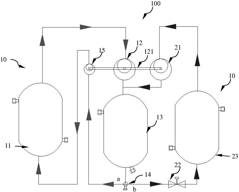
[0020] figure 1 It is a schematic diagram of the heat-driven non-electric vapor compression refrigeration device of this embodiment.

[0021] Such as figure 1 As shown, a heat-driven non-electric vapor compression refrigeration device 100 has a high-pressure driving circuit 10 and a low-pressure refrigeration circuit 20 .

[0022] The high-pressure driving circuit 10 has a steam generator 11 , an expander 12 , a condenser 13 , a diverter valve 14 , and a working medium pump 15 that are sequentially connected through pipelines.

[0023] Wherein, the steam generator 11 has a sandwich structure with an inner cavity and a jacket layer, the inner cavity is used for circulating refrigerant, and the jacket layer of the steam generator 11 is used for circulating an external heat source.

[0024] The expander 12 has an inlet, an outlet, and an expander output shaft 121, and the expander output shaft 121 is used to output power outward.

[0025] The condenser 13 has a sandwich struct...

Embodiment 2

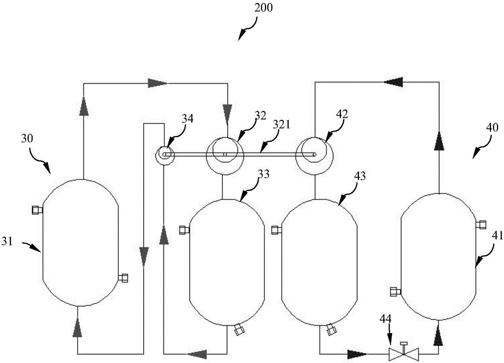
[0044] image 3 It is a schematic diagram of the heat-driven non-electric vapor compression refrigeration device of this embodiment.

[0045] In Embodiment 1, the high-pressure drive circuit and the low-pressure refrigeration circuit share a condenser, and the liquid refrigerant in the two circuits is distributed through a diverter valve.

[0046] In this embodiment, the heat-driven non-electric vapor compression refrigeration device 100 has two circuits, the high-pressure drive circuit 30 and the low-pressure refrigeration circuit 40, which are independent of each other. Such as image 3 As shown, the specific structure and working principle are similar to those of Embodiment 1. The expander output shaft 321 on the expander 32 is connected with the working medium pump 34 and the compressor 42 to drive them to run.

[0047] High voltage drive circuit 30 . The steam generator 31 communicates with the inlet of the expander 32 through a high-pressure pipeline, and the outlet ...


PUM


Abstract

A non-electric vapor compression refrigeration device driven by thermal energy, which is used to feed in external heat sources for compression and refrigeration to output brine. A steam generator, an expander, and a condenser connected by pipelines, wherein the expander is used to convert the energy of the high-pressure steam into kinetic energy and output from the output shaft of the expander; Flow valve and evaporator. The evaporator is used for evaporating and absorbing heat to output the cooled brine. The condenser is respectively connected with the outlet of the compressor and the inlet of the throttle valve through pipelines. Among them, the output shaft of the compressor and the expander Connection for the operation of the compressor driven by the output shaft of the expander. Due to the high-pressure driving circuit, the compressor and the working medium pump are driven by using the high-pressure steam generated by the steam generator to drive the kinetic energy generated by the expander, and all electricity is consumed.

Description

technical field [0001] The invention relates to a vapor compression refrigeration device, in particular to a refrigeration device which utilizes thermal energy to drive the evaporation of an organic working medium, and then drives an expander to generate power, and belongs to the field of refrigeration machinery. Background technique [0002] Existing commercial and residential refrigeration devices are mainly vapor compression refrigeration devices driven by electric energy, but with the increasingly serious environmental problems and the increase of electricity load in summer, the production of thermal energy generated by solar energy and industrial emissions Equipment that uses waste heat as the driving force and makes it produce refrigeration will become an effective way to solve energy problems. [0003] However, the existing heat-powered refrigeration technologies are mainly lithium bromide absorption refrigeration technology, ammonia water absorption refrigeration, an...

Claims


Application Information

Patent Timeline
IPC IPC(8): F25B9/06
CPCF25B9/065
Inventor 吴腾马柳建华孟照峰汪涛陈红群
Owner UNIV OF SHANGHAI FOR SCI & TECH
Why Eureka
Try Eureka