Intelligent label connector

A technology of smart labels and connectors, applied in the direction of connection, parts of connection devices, contact parts, etc., can solve problems such as unfavorable market competitiveness, complex assembly process, inconvenient maintenance, etc., to ensure stability and communication quality, Guaranteed communication quality and easy assembly

Active Publication Date: 2016-07-20
DONGGUAN YUQIU ELECTRONICS CO LTD
View PDF3 Cites 2 Cited by
  • Summary
  • Abstract
  • Description
  • Claims
  • Application Information

AI Technical Summary

Problems solved by technology

In actual use, since the structure of the fiber box is standardized, after the fiber optic adapter is installed in the box, there is a very thin assembly space between the upper end of the fiber adapter and the upper end of the box, and because the PCB The thickness of the board is relatively large, so that the PCB board can only be assembled on the lower end of the fiber optic adapter. When replacing the PCB board, the PCB board must be disassembled first, which is not convenient for later maintenance
[0005] In addition, the electronic label can also be connected to the control line through the label connector. Specifically, the label connector is provided with a control line interface for connecting the control line and an electronic label interface for connecting the electronic label. The LED displayed is fixed by welding the built-in wire of the label connector and the terminal in the control line interface. Since the LED of the label connector needs to emit light from the side, it is not suitable for the assembly method of using the robot to pick up the LED and assemble it by lifting. The label connector assembles the LED, that is to say, the assembly of the above-mentioned LED and the welding of the wires are all done manually. The entire assembly process is relatively complicated, the efficiency is low, and it is difficult to disassemble and assemble, which is not conducive to improving the market competitiveness of the product.

Method used


Image

  • Intelligent label connector
  • Intelligent label connector
  • Intelligent label connector

Examples


Embodiment Construction

[0062] The present invention will be further described below in conjunction with specific embodiments and accompanying drawings.

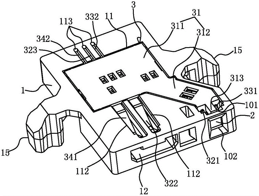
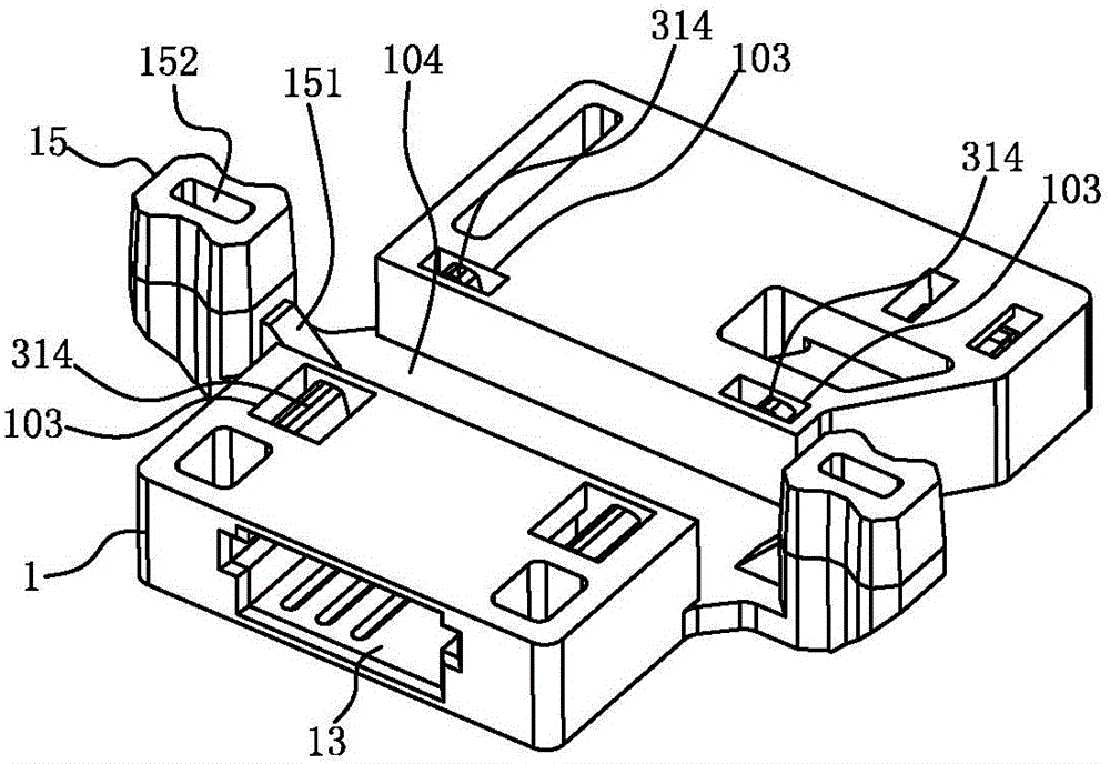
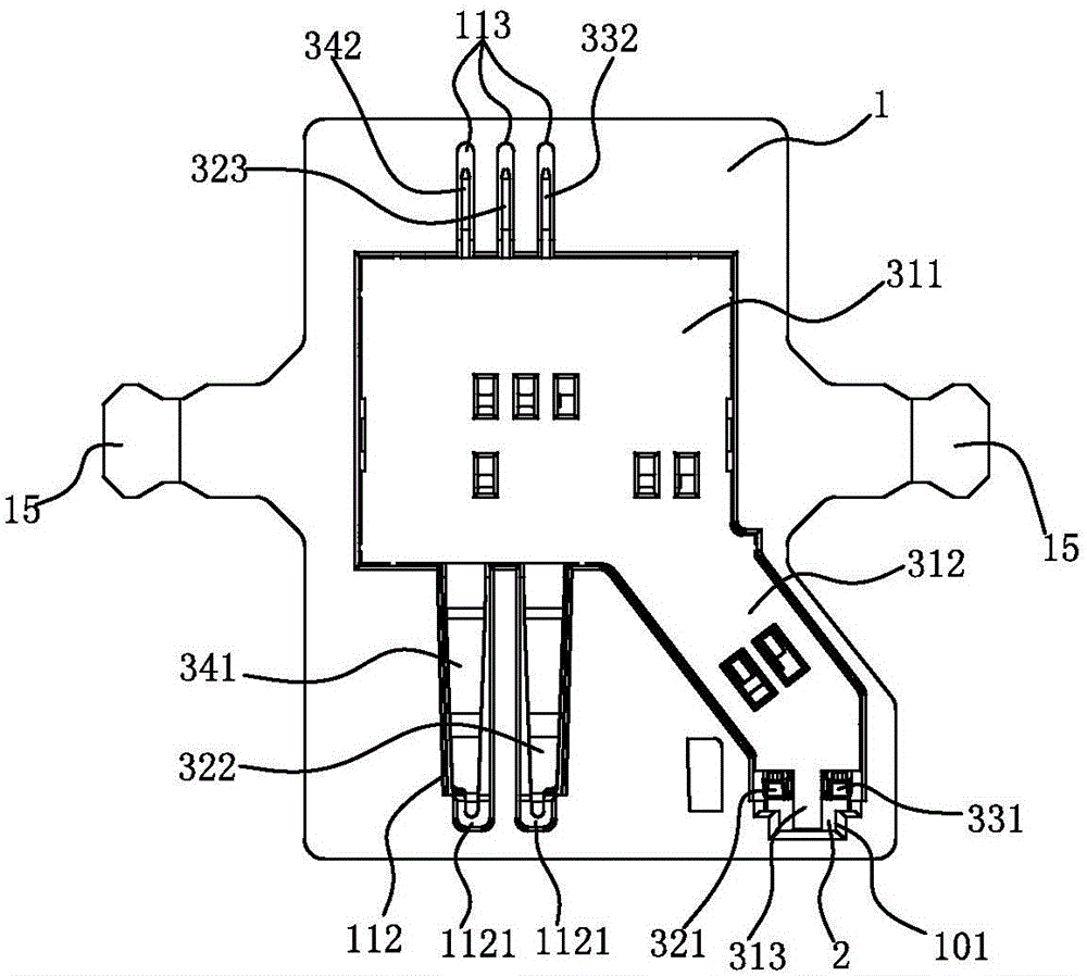
[0063] See Figure 1-3 Shown is a smart label connector, which includes: a flat plastic seat 1 , at least one LED chip 2 installed in the plastic seat 1 and a terminal assembly 3 installed in the plastic seat 1 .

[0064] The plastic seat 1 is provided with an accommodating groove 11 for the assembly of the terminal assembly 3 and first and second insertion ports 12 and 13 communicating with the accommodating groove 11. The connection ports 12 and 13 are respectively used for docking with electronic tags and control lines.

[0065] The LED chip 2 is inserted and installed in the plastic seat 1 along its side; specifically, the plastic seat 1 is provided downward along its upper end to communicate with the accommodating groove 11 and fit the shape of the LED chip 2. The insertion position 101, and the plastic seat 1 is provided with a window 102 t...


PUM


Abstract

The invention discloses an intelligent label connector. The connector comprises a plastic seat, an LED chip and a terminal assembly, wherein the plastic seat is provided with an accommodation groove, a first plug port and a second plug port; the LED chip is installed in the plastic seat; the terminal assembly includes a terminal seat installed in the accommodation groove, a power supply terminal, a grounding terminal and a signal terminal, and the power supply terminal, the grounding terminal and the signal terminal are arranged in the terminal seat; a first elastic contact arm of the power supply terminal and an elastic conduction connection arm in the grounding terminal abut against a positive electrode and a negative electrode of the LED chip respectively so as to form non-welding-type conduction connection; a second elastic contact arm of the power supply terminal and an elastic plug arm of the signal terminal are inserted into the first plug port; and first, second and third contact portions of the power supply terminal, the grounding terminal and the signal terminal are inserted into the second plug port. When the terminal assembly is inserted, embedded and fixed into the plastic seat from top to bottom, the first elastic contact arm and the elastic conduction connection arm abut against and contact with the positive electrode and the negative electrode of the LED chip respectively so as to form non-welding-type conduction connection and lead welding is not needed. Therefore, structure complexity and assembling difficulty of the structure are simplified.

Description

Technical field: [0001] The invention relates to the technical field of connector products, in particular to an intelligent label connector. Background technique: [0002] Optical fiber communication is a communication method that uses light waves as a carrier and optical fiber as a transmission medium to transmit information from one place to another. It is called "wired" optical communication. Nowadays, optical fiber has become the main transmission mode in the world communication because of its wide transmission frequency bandwidth, high anti-interference and low signal attenuation, which is far superior to the transmission of cable and microwave communication. In optical fiber communication technology, it is the most common way to realize the connection between optical fibers through optical fiber adapters and optical fiber plugs. [0003] In actual use, a plurality of optical fiber adapters are set in a fiber-container box, and then the fiber-container box is installed...

Claims


Application Information

Patent Timeline
Patent Type & Authority Applications(China)
IPC IPC(8): H01R13/40H01R13/02H01R13/05H01R13/717
CPCH01R13/02H01R13/05H01R13/40H01R13/7175
Inventor 李忠国万军李克辉周侗彭雪胡光才
Owner DONGGUAN YUQIU ELECTRONICS CO LTD
Why Eureka
Try Eureka