A drop-out fuse auxiliary installation device

A drop-type fuse, installation device technology, applied in switchgear, electrical components and other directions, can solve the problems of unreasonable installation angle, uneven installation process, low voltage level, etc., to achieve good fixation, ensure normal work, The effect of difficult relative motion

Inactive Publication Date: 2017-09-19
ZHANGQIU POWER SUPPLY CO OF STATE GRID SHANDONG ELECTRIC POWER CO +1
View PDF6 Cites 0 Cited by
  • Summary
  • Abstract
  • Description
  • Claims
  • Application Information

AI Technical Summary

Problems solved by technology

At present, dropout fuses have different models and manufacturers, the voltage level is not high, the installation process is uneven, and the installation angle is not reasonable. In addition, the operating environment of the installation site is also different, so it is directly installed on the cross arm. , will cause the drop-out fuse to fail to effectively drop after the fuse is blown to cut off the fault, resulting in the expansion of the scope of the accident and causing huge losses. Therefore, it is necessary to develop an auxiliary installation device to ensure a firm and reliable fixation of the drop-out fuse While installed on the cross arm, the installation angle can be flexibly adjusted according to the actual needs of the operation site to ensure the normal operation of the dropout fuse

Method used


Image

  • A drop-out fuse auxiliary installation device
  • A drop-out fuse auxiliary installation device
  • A drop-out fuse auxiliary installation device

Examples


Embodiment 1

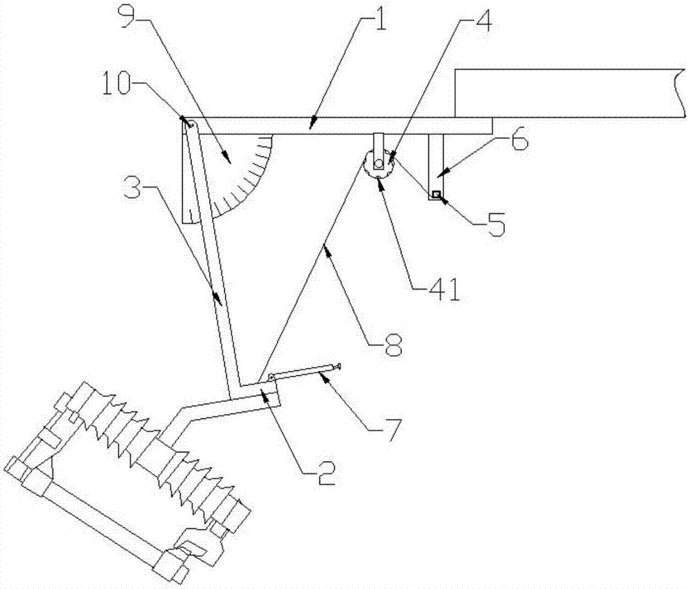
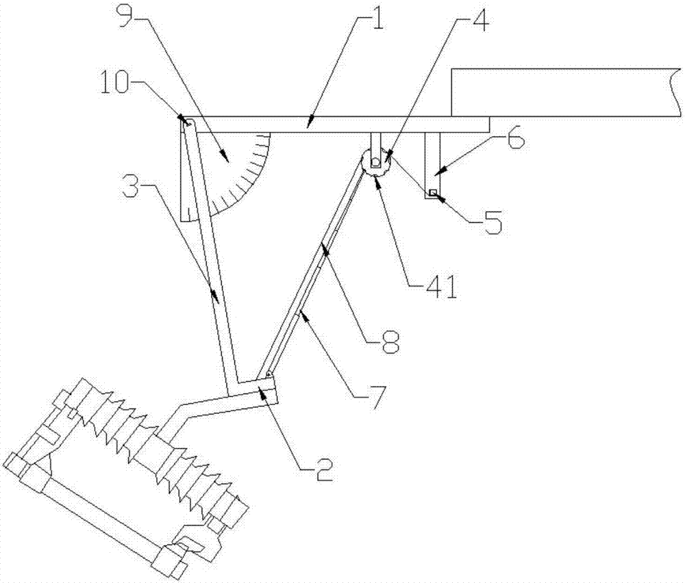
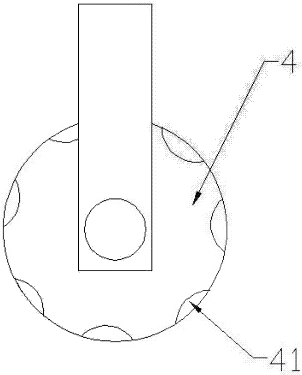
[0032] Such as Figures 1 to 5 As shown, a drop-out fuse auxiliary installation device includes a top plate 1, the top plate 1 is parallel to the cross arm, the right end of the top plate 1 is fixedly connected with the cross arm, the left end of the top plate 1 is connected to the rotating rod 3 through a rotating shaft 10, and the top plate 1 The lower part is provided with a rotating rod 3, a fixed pulley 4 and an insertion rod 6 in sequence from left to right. The lower end of the rotating rod 3 is connected to the connecting plate 2 perpendicular to it, and the lower surface of the connecting plate 2 is engaged with the lower surface of the drop-out fuse. One end of the cable 8 passing through the fixed pulley 4 is connected to the connecting plate 2, and the other end is connected to the side wall of the winding column 5. The insertion rod 6 is provided with a device for inserting the winding column 5 and restricting its rotation. Limiting jacks, the two radial faces of ...


PUM


Abstract

The invention discloses an auxiliary mounting apparatus for a drop fuse. The auxiliary mounting apparatus comprises a top plate, wherein the right end part of the top plate is fixedly connected with a cross arm; the left end of the top plate is connected with a rotary rod through a rotary shaft; the rotary rod, a fixed pulley and an insertion rod are arranged at the lower part of the top plate in sequence from left to right; the lower end of the rotary rod is connected with a connecting plate; the connecting plate is connected with the drop fuse; one end of a cable rope penetrating through the fixed pulley is connected with the connecting plate while the other end of the cable rope is connected with a side wall of a winding column; a limiting insertion hole for limiting rotation of the winding column is formed in the insertion rod; a plurality of insertion holes are uniformly formed in the periphery of each of two radial surfaces of the fixed pulley; and a telescopic insertion rod is mounted on the upper surface of the connecting plate in a manner of corresponding to the insertion holes in the periphery of each of the two radial surfaces of the fixed pulley. The apparatus is mounted between the drop fuse and the cross arm, the drop fuse can be firmly mounted on the cross arm, and a mounting angle of the drop fuse can be conveniently and flexibly adjusted according to actual needs of an operation site to ensure the drop fuse to normally work.

Description

technical field [0001] The invention relates to a drop-out fuse installation auxiliary device, in particular to a drop-out fuse which is installed between the drop-out fuse and the cross arm and can adjust the installation angle of the drop-out fuse according to actual application requirements. Auxiliary installation of fuses. Background technique [0002] Drop-out fuse is the most commonly used short-circuit protection switch for branch lines of 10kV distribution lines and distribution transformers. It is economical, easy to operate, and adaptable to outdoor environments. It is widely used in 10kV distribution lines and power distribution The primary side of the transformer is used for protection and equipment switching and switching operations. The drop-out fuse is installed on the branch line of the 10kV distribution line, which can reduce the scope of power outages. Because it has an obvious disconnection point, it has the function of an isolating switch, creating a saf...

Claims


Application Information

Patent Timeline
Patent Type & Authority Patents(China)
IPC IPC(8): H02B3/00
CPCH02B3/00
Inventor 翟强高国美杨学静王善东张孝宾寿洪樱李凤贤刘聪
Owner ZHANGQIU POWER SUPPLY CO OF STATE GRID SHANDONG ELECTRIC POWER CO
Why Eureka
Try Eureka