Rotor of high-speed Halbach-type permanent magnet motor

A permanent magnet motor, high-speed technology, applied in the direction of magnetic circuit rotating parts, magnetic circuits, electrical components, etc., can solve the problems of reducing the power density of the motor, reducing the power density of the motor, reducing the magnetic density of the air gap of the motor, and achieving improved Dynamic response capability, improved power density, and the effect of preventing loosening

Inactive Publication Date: 2016-07-20
HARBIN INST OF TECH
View PDF10 Cites 11 Cited by
  • Summary
  • Abstract
  • Description
  • Claims
  • Application Information

AI Technical Summary

Problems solved by technology

If the sheath is too thick, it will increase the reluctance of the motor magnetic circuit, reduce the air gap flux density of the motor, and reduce the power density of the motor; if the interference is too large, the temperature of the sheath heat sleeve will be higher, and the permanent magnet will lose magnetism dangers and pitfalls
Or to prevent circumferential movement, add inlaid material between permanent magnets, which will reduce the power density of the entire motor

Method used


Image

  • Rotor of high-speed Halbach-type permanent magnet motor
  • Rotor of high-speed Halbach-type permanent magnet motor
  • Rotor of high-speed Halbach-type permanent magnet motor

Examples


Embodiment 1

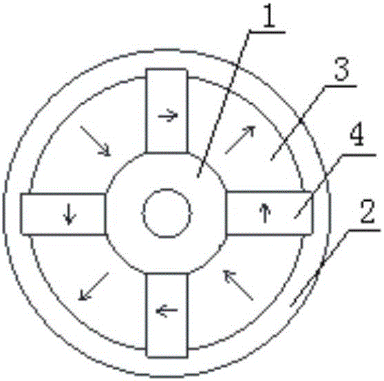
[0028] Example 1, such as figure 1 As shown, the outside of the strip-shaped rectangular permanent magnet 4 is higher than the adjacent strip-shaped arc-shaped permanent magnet 3, and the rotor sheath 1 is provided with concave holes corresponding to the strip-shaped rectangular permanent magnet 4. or correspondingly, the outside of the strip-shaped arc-shaped permanent magnet 3 is higher than the adjacent strip-shaped rectangular permanent magnet 4, and the rotor sheath 1 is provided with the bar-shaped arc-shaped permanent magnet 3 the corresponding groove.

Embodiment 2

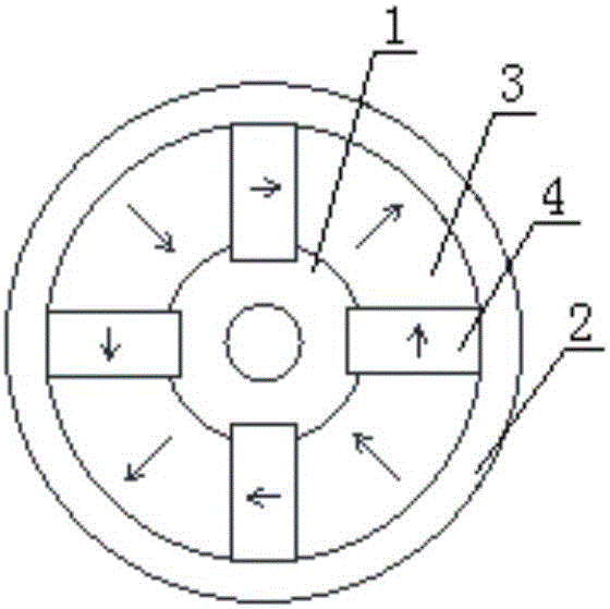
[0029] Example 2, such as figure 2 As shown, the inside of the strip-shaped rectangular permanent magnet 4 protrudes from the adjacent strip-shaped arc-shaped permanent magnet 3, and the rotor shaft 1 is provided with a groove corresponding to the strip-shaped rectangular permanent magnet 4 or correspondingly, the inside of the strip-shaped arc-shaped permanent magnet 3 protrudes from the adjacent strip-shaped rectangular permanent magnet 4, and the rotor shaft 1 is provided with a set corresponding to the strip-shaped arc-shaped permanent magnet 3 groove.

Embodiment 3

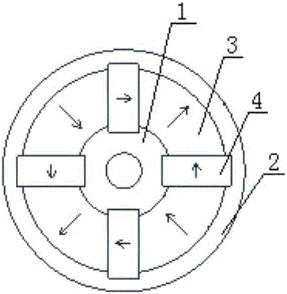
[0030] Example 3, such as image 3 As shown, the outside and inside of the strip-shaped rectangular permanent magnet 4 are higher than the adjacent strip-shaped arc-shaped permanent magnet 3, and the rotor shaft 1 and the rotor sheath 2 are provided with The corresponding groove of the permanent magnet 4; or correspondingly, the outside and the inside of the strip-shaped arc-shaped permanent magnet 3 are higher than the adjacent strip-shaped rectangular permanent magnet 4, and the rotor shaft 1 and the rotor sheath 2 is provided with a groove corresponding to the strip arc permanent magnet 3.


PUM


Abstract

The invention provides a rotor of a high-speed Halbach-type permanent magnet motor. The rotor comprises a Halbach-type permanent magnet structure, a rotor shaft and a rotor sheath, wherein the Halbach-type permanent magnet structure comprises strip-shaped rectangular permanent magnets and strip-shaped arc permanent magnets; the external surfaces of the strip-shaped arc permanent magnets are arc-shaped; the strip-shaped rectangular permanent magnets and the strip-shaped arc permanent magnets are arranged in the peripheral direction of the rotor shaft at intervals; the rotor sheath is arranged outside the strip-shaped rectangular permanent magnets and the strip-shaped arc permanent magnets; the adjacent strip-shaped rectangular permanent magnets and strip-shaped arc permanent magnets are directly laminated; and a groove corresponding to the strip-shaped rectangular permanent magnets or the strip-shaped arc permanent magnets is formed in the rotor shaft or the rotor sheath. Due to the structural design of the rotor, the numerical value of the air-gap flux density of the rotor is improved; the sine degree of the waveform is enhanced; the power density of the motor is improved; the flux density of a rotating shaft yoke is reduced; the hollow rotating shaft provides a cooling channel for the rotor; and the dynamic response ability of the rotor is improved.

Description

technical field [0001] The invention relates to a rotor of a high-speed Halbach type permanent magnet motor. Background technique [0002] In the high-speed Halbach type permanent magnet motor in the prior art, in order to prevent the permanent magnets of the rotor from falling off and moving relative to the sheath shaft in the circumferential direction, it is usually necessary to reinforce the permanent magnets on the rotor. The common method of reinforcement is to heat-shrink a high-strength alloy or composite material sheath on the outer surface of the permanent magnet, which requires that the sheath not only have sufficient thickness, but also have sufficient interference with the surface of the permanent magnet. If the sheath is too thick, it will increase the reluctance of the motor magnetic circuit, reduce the air gap flux density of the motor, and reduce the power density of the motor; if the interference is too large, the temperature of the sheath heat sleeve will b...

Claims


Application Information

Patent Timeline
Patent Type & Authority Applications(China)
IPC IPC(8): H02K1/27H02K1/32H02K1/28
CPCH02K1/2773H02K1/28H02K1/32
Inventor 李立毅于吉坤张江鹏曹继伟
Owner HARBIN INST OF TECH
Why Eureka
Try Eureka