Sampling frequency offset compensation device and method
A sampling frequency deviation and compensation device technology, applied in the field of communication, can solve problems such as sampling frequency deviation, sound or music distortion, and user experience deterioration
- Summary
- Abstract
- Description
- Claims
- Application Information
AI Technical Summary
Problems solved by technology
Method used
Image
Examples
no. 1 example
[0032] see figure 2 , the sampling frequency offset compensation device includes: a phase locked loop 21 , a sampling frequency offset estimation module 22 and a sampling frequency offset compensation module 23 .
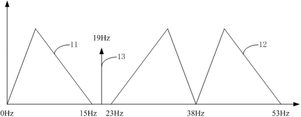
[0033] The transmitted signal of the stereo FM broadcast, that is, the signal received by the stereo FM broadcast receiver is an analog signal. However, in order to be able to process the transmitted signal of the stereo FM broadcast using a common digital platform and demodulate a high-quality stereo audio signal from the transmitted signal, high-frequency sampling is used in the radio frequency front end of the stereo broadcast receiver Signal samples the received signal. After sampling the received signal, the received signal is processed in the discrete time domain.
[0034] However, due to interference, noise and other factors, the sampling signal for sampling the received signal often has a frequency offset, resulting in inaccurate sampling results for the ...
no. 2 example
[0046] This embodiment provides a technical solution of a sampling frequency offset compensation device on the basis of the foregoing embodiments. In addition to the phase-locked loop 33 , the sampling frequency offset estimation module 35 and the sampling frequency offset compensation module 36 , the technical solution includes: a time domain to frequency domain conversion module 31 , a bandpass filter 32 and a sample synchronization module 34 .
[0047] see image 3 , The sampling frequency offset compensation device includes: a time-domain to frequency-domain conversion module 31 , a bandpass filter 32 , a phase-locked loop 33 , a sample synchronization module 34 , a sampling frequency offset estimation module 35 and a sampling frequency offset compensation module 36 .
[0048] The time domain to frequency domain module 31 is used to convert the input time domain signal into a frequency domain signal.
[0049] The time-domain to frequency-domain conversion module 31 is used ...
no. 3 example
[0069] This embodiment provides a technical solution of a phase-locked loop on the basis of the above-mentioned embodiments. device 66.
[0070] see Figure 6 , the multiplier 61 is used to multiply the obtained pilot signal by the same-frequency reference signal.
[0071] The reference signal having the same frequency as the pilot signal has a phase difference of π / 2 from the pilot signal. If the pilot signal is a 19kHz sine signal, the reference signal is a 19kHz cosine signal. The relationship between the multiplication of the pilot signal and the reference signal is given by formula (2):
[0072] θ ( kT ) = sin ( ωkT + α ) · cos ( ωkT + β ) = 1 2 [ sin ...
PUM
 Abstract
Description
Claims
Application Information
 - R&D
- Intellectual Property
- Life Sciences
- Materials
- Tech Scout
- Unparalleled Data Quality
- Higher Quality Content
- 60% Fewer Hallucinations
Browse by: Latest US Patents, China's latest patents, Technical Efficacy Thesaurus, Application Domain, Technology Topic, Popular Technical Reports.
© 2025 PatSnap. All rights reserved.Legal|Privacy policy|Modern Slavery Act Transparency Statement|Sitemap|About US| Contact US: help@patsnap.com


