Spiral clamping-type vessel dilator assembly

A vascular expansion and clamping technology, applied in the field of medical devices, can solve the problems of operation failure, installation and operation difficulties, etc., and achieve the effects of simple structure, convenient operation and wide application range.

Inactive Publication Date: 2016-07-27
QINGDAO MUNICIPAL HOSPITAL
View PDF8 Cites 0 Cited by
  • Summary
  • Abstract
  • Description
  • Claims
  • Application Information

AI Technical Summary

Problems solved by technology

However, due to the one-piece fixed structure of the support rod, it is very difficult to install and release the two ends of the monofilament on the support rod, and it is easy to bring out the half-released monofilament during the process of pulling out the support rod, resulting in failure of the operation

Method used


Image

  • Spiral clamping-type vessel dilator assembly
  • Spiral clamping-type vessel dilator assembly
  • Spiral clamping-type vessel dilator assembly

Examples


Embodiment Construction

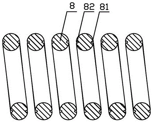
[0014] Such as figure 1 As shown, the helically clamped vascular dilator assembly of the present invention includes a dilator body formed by helically coiling a columnar monofilament 8 and a clamping tool for clamping the dilator body. The upper part of the monofilament 8 , The lower sides are symmetrically provided with draw-in slots 81, 82, the cross-sections of the draw-in slots 81, 82 are isosceles triangles, and the columnar helix formed by the draw-in slots 81, 82 is coaxial with the columnar helix formed by the monofilament 8. And the axes of the locking grooves 81 and 82 are parallel to the axis of the monofilament 8 .

[0015] The monofilament 8 has a cylindrical structure, and the connecting line between the bottoms of the two slots 81 and 82 and the center of the monofilament 8 forms an included angle of 150°-180°.

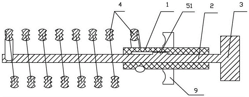
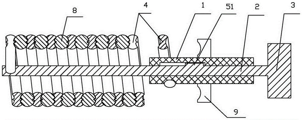
[0016] Such as figure 2 As shown, the clamping tool includes a handle 1 and a push rod 2 inserted in the handle 1 to move axially. The rear end of t...


PUM


Abstract

The invention relates to a medical tool, in particular to a spiral clamping-type vessel dilator assembly. The spiral clamping-type vessel dilator assembly comprises a spiral vessel dilator body and a clamping tool for clamping the dilator body. The clamping tool comprises a handle and a pushing rod which is inserted into the handle and can move in the axial direction; a pressing plate is arranged at the back end of the pushing rod, the pushing rod is sleeved with spiral clamping sleeves, the spiral clamping sleeves are formed by spirally twisting special-shaped single wires, upper clamping spiral parts and lower clamping spiral parts are symmetrically arranged at the upper ends and the lower ends of the cross sections of the special-shaped single wires, one ends of the special-shaped single wires are fixedly connected to the front end of the pushing rod, and the other ends of the special-shaped single wires are fixedly connected to the handle. The tool is simple in structure, convenient to operate and wide in application range.

Description

technical field [0001] The invention relates to a medical appliance, in particular to a spiral clamping blood vessel dilator assembly. Background technique [0002] At present, the commonly used cardiovascular dilation surgery is mainly to install stents or balloons. Since the cardiovascular pipeline is relatively thin, the operation during the operation is very troublesome. It takes a lot of time and energy to install and adjust the position of the stent, which brings difficulty and risk to the operation. Chinese patent 2010202319042 discloses a "cardiovascular dilation device" in which the mesh stent is installed in a guide tube in advance, and a stylet is also installed in the guide tube. During the operation, the guide tube is first implanted into the blood vessel, and then Use the die to push out the mesh support. Although this "cardiovascular dilation device" can simplify the operation to a certain extent and improve the accuracy of the mesh stent in place, its scope...

Claims


Application Information

Patent Timeline
Patent Type & Authority Applications(China)
IPC IPC(8): A61B17/22
CPCA61B17/22A61B2017/22001
Inventor 侯伟娜
Owner QINGDAO MUNICIPAL HOSPITAL
Why Eureka
Try Eureka