Improved structure of clamping device

A technology of clamping device and clamping surface, which is applied in the direction of cleaning methods and utensils, chemical instruments and methods, etc., can solve the problems of inconvenient operation of the clamping structure, achieve uniform force balance, improve stability, and improve convenience Effect

Inactive Publication Date: 2016-07-27
CHENGDU DAMO PETROLEUM MACHINERY GRP
View PDF5 Cites 2 Cited by
  • Summary
  • Abstract
  • Description
  • Claims
  • Application Information

AI Technical Summary

Problems solved by technology

[0004] The purpose of the present invention is to provide an improved structure of the clamping device to solve the problem that the existing clamping structure is not easy to operate

Method used


Image

  • Improved structure of clamping device
  • Improved structure of clamping device

Examples


Embodiment 1

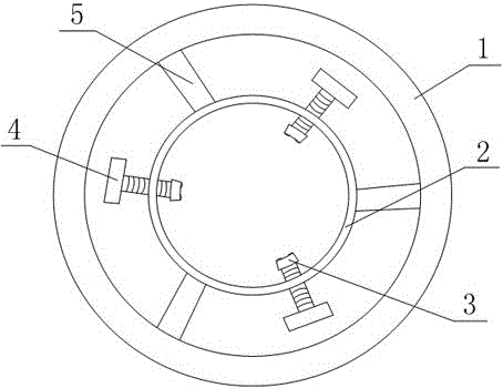
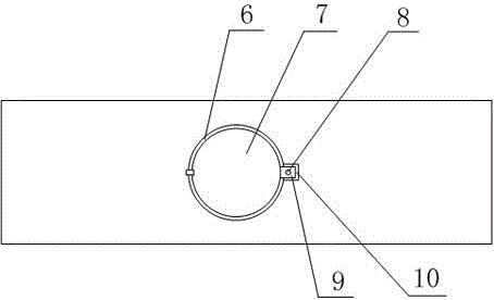
[0032] Such as figure 1 , figure 2 As shown, an improved structure of a clamping device includes an outer ring 1 and an inner ring 2, the inner ring 2 is located inside the outer ring 1, and the outer ring 1 and the inner ring 2 are concentric rings, The outer ring 1 is fixedly connected with the inner ring 2 through a connecting rod 5, and the inner ring 2 is provided with 3 threaded through holes, and the threaded through holes are provided with bolts 4 matching with the threaded through holes, The outer ring 1 is provided with a through hole 6, one end of the cover plate 7 is hinged with the inner wall of the through hole 6, and the other end is provided with a lug 9, the lug 9 is provided with a fixed through hole, and the outer ring 1 is provided with a The groove 10 that cooperates with the lug 9, the bottom of the groove 10 is provided with a threaded hole that matches the fixed through hole, the cover plate 7 is fixed on the outer ring 1 through the cooperation of th...

Embodiment 2

[0034] Such as figure 1 , figure 2 As shown, this embodiment is based on Embodiment 1, and one end of the inner ring 2 of the bolt 4 is provided with a clamping block 3, and the clamping surface of the clamping block 3 is provided with 4 hemispherical protrusions; 4 hemispherical The hemispherical protrusions are all arranged at 4 diagonal corners of the clamping surface; the diameter of the hemispherical protrusion is 1 / 3 of the width of the clamping surface; the straight line where the connecting rod 5 is located coincides with the diameter of the outer ring 1 There are 3 connecting rods 5, and the connecting rods 5 are equally spaced on the inner ring 2.


PUM


Abstract

The invention discloses an improved structure of a clamping device. The clamping device comprises an outer ring and an inner ring, the inner ring is located in the outer ring, and the outer ring and the inner ring are concentric rings. The outer ring and the inner ring are fixedly connected through connecting rods. The inner ring is provided with at least one threaded through hole, and a bolt is arranged in each threaded through hole in a matched mode. The outer ring is provided with a through hole, one end of a cover plate is hinged to the inner wall of the through hole, a protruding piece is arranged at the other end of the cover plate and provided with a fixing through hole, the outer ring is provided with a groove matched with the protruding piece, and a threaded hole matched with the fixing through hole is formed in the bottom of the groove. The cover plate is fixed to the outer ring through matching of a bolt I and the threaded hole, and the through hole corresponds to the bolts. By means of the improved structure of the clamping device, the problem that an existing clamping structure is not convenient to operate.

Description

technical field [0001] The invention relates to a petroleum mechanical processing device, in particular to an improved structure of a clamping device. Background technique [0002] In the process of oil extraction, the drill pipe is an indispensable tool. The drill pipe can be used repeatedly. In order to improve the service life of the drill pipe, the drill pipe must be maintained and cleaned after each use. During the use of the drill pipe, the mud, stone chips, oil stains and other debris generated by drilling will adhere to the outer wall of the drill pipe, corrode the outer wall of the drill pipe, affect the service life of the drill pipe, and damage the drill pipe. The next use will be affected, and the drill pipe with debris attached will affect the quality and work efficiency of the next drilling. Therefore, the drill pipe must be cleaned after use. [0003] Due to the long length of the drill pipe used in petroleum machinery, due to gravity, the middle part of the ...

Claims


Application Information

Patent Timeline
Patent Type & Authority Applications(China)
IPC IPC(8): B08B13/00
CPCB08B13/00
Inventor 贺昶明
Owner CHENGDU DAMO PETROLEUM MACHINERY GRP
Why Eureka
Try Eureka