An automatic clamping device

An automatic clamping and pressing arm technology, applied in workpiece clamping devices, auxiliary devices, positioning devices, etc., can solve the problems of heavy weight, high price, complex structure, etc., to reduce parts and volume, reduce weight and volume , the effect of simple structure

Inactive Publication Date: 2016-07-27
TIANJIN WEIKE WODE TECH
View PDF0 Cites 4 Cited by
  • Summary
  • Abstract
  • Description
  • Claims
  • Application Information

AI Technical Summary

Problems solved by technology

[0002] In welding fixtures, processing fixtures and automation, it is usually necessary to use clamping devices to clamp parts. Although the existing clamping devices are also realized by pneumatic control, their structures are complicated, expensive, large in size and heavy in weight. It is beneficial to the use of welding fixtures, processing fixtures, and automation equipment; and due to its structural limitations, the operating sensitivity of the clamping device is low, which cannot fully meet the needs of automated production

Method used


Image

  • An automatic clamping device
  • An automatic clamping device
  • An automatic clamping device

Examples


Embodiment 1

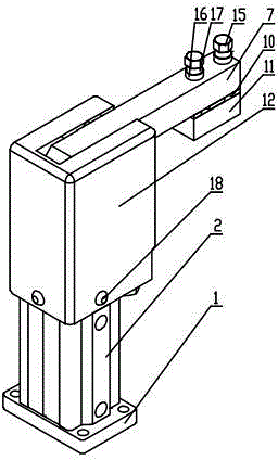
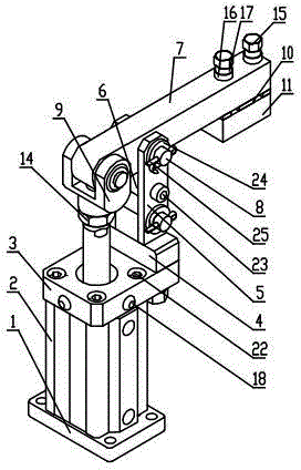
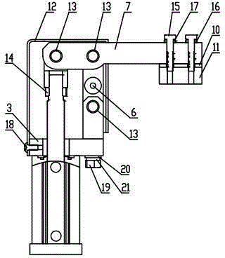
[0011] The present invention includes a base 1, a cylinder 2, a connecting seat 3, a connecting rod seat 4, a connecting rod 5, a connecting column 6, a pressing arm 7, a pin shaft 8, a Y-shaped joint 9, an adjusting gasket 10, a pressing block 11, a protective Cover 12, copper sleeve 13, lock nut 14, A screw 15, A flat washer 16, A spring washer 17, round head screw 18, B screw 19, B flat washer 20, B spring washer 21, C screw 22, D Screw 23, pin shaft flat pad 24, cotter pin 25, when installing, first install the cylinder 2 on the upper end of the base 1, fix the connecting seat 3 on the upper end of the cylinder 2 through the C screw 22, and then pass the B screw 19 through the B The spring washer 21 and the B flat washer 20 install the connecting rod seat 4 on the upper end of the connecting seat 3, set the two connecting rods 5 symmetrically on the upper end of the connecting rod seat 4, and fix the connecting column 6 on the two connecting rods through the D screw 23. Th...

Embodiment 2

[0013] When in use, first adjust the clamping position by adjusting the gasket 10, and the cylinder 2 moves upwards, thereby pushing the Y-shaped joint 9 upwards, driving the clamping arm 7 to perform a 90-degree rotation, and clamping and releasing the workpiece. The protective cover 12 protects the operating mechanism inside it.


PUM


Abstract

The invention provides an automatic clamping device which is flexible to operate. The automatic clamping device comprises a pedestal, an air cylinder, a connecting base, a connecting rod base, connecting rods, and a connecting pillar. The air cylinder is installed at the upper end of the pedestal; the connecting base is fixedly installed to the upper end of the air cylinder via C screws; a protection shield is installed on the upper end of the connecting base via round head screws; B screws penetrate a B spring washer and a B flat washer to install the connecting rod base to the upper end of the connecting base; the two connecting rods are arranged on the upper end of the connecting rod base symmetrically; the connecting pillar is fixedly installed between the two connecting rods via D screws to fixedly connect the two connecting rods together; a Y-shaped joint is installed on the upper end of the air cylinder via a locking nut. The pneumatic device is used as the connecting member, so that the parts of the structure are reduced and the size of the structure is reduced; the automatic clamping device is simple in structure; the weight and the size are reduced; based on the lever principle, the 90-degree rotation movement of a pressing arm is realized, so that clamping movement and releasing movement are more flexible.

Description

technical field [0001] The invention relates to the field of mechanical equipment, in particular to an automatic clamping device. Background technique [0002] In welding fixtures, processing fixtures and automation, it is usually necessary to use clamping devices to clamp parts. Although the existing clamping devices are also realized by pneumatic control, their structures are complex, expensive, large in size and heavy in weight. It is beneficial to the use of welding jigs, processing jigs, and automation equipment; and due to its structural limitation, the operation sensitivity of the clamping device is low, which cannot fully meet the needs of automated production. Contents of the invention [0003] According to the above technical problems, the present invention provides an automatic clamping device with flexible operation, which is characterized in that it includes a base, a cylinder, a connecting seat, a connecting rod seat, a connecting rod, a connecting column, a ...

Claims


Application Information

Patent Timeline
Patent Type & Authority Applications(China)
IPC IPC(8): B23K37/04B23Q3/08B25B11/00
Inventor 董英
Owner TIANJIN WEIKE WODE TECH
Why Eureka
Try Eureka