Clamping claw device for assembling O-shaped ring

An O-ring and clamping jaw technology, applied in the field of clamping jaw devices for O-ring assembly, can solve problems such as low operation efficiency, and achieve the effects of quick installation, compact internal space and small structure

Active Publication Date: 2016-07-27
BOZHON PRECISION IND TECH CO LTD
View PDF7 Cites 11 Cited by
  • Summary
  • Abstract
  • Description
  • Claims
  • Application Information

AI Technical Summary

Problems solved by technology

[0003] The technical problem solved by the present invention: the O-ring is set on the

Method used


Image

  • Clamping claw device for assembling O-shaped ring
  • Clamping claw device for assembling O-shaped ring
  • Clamping claw device for assembling O-shaped ring

Examples


Embodiment Construction

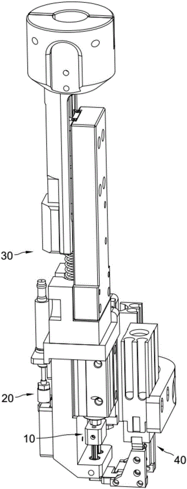
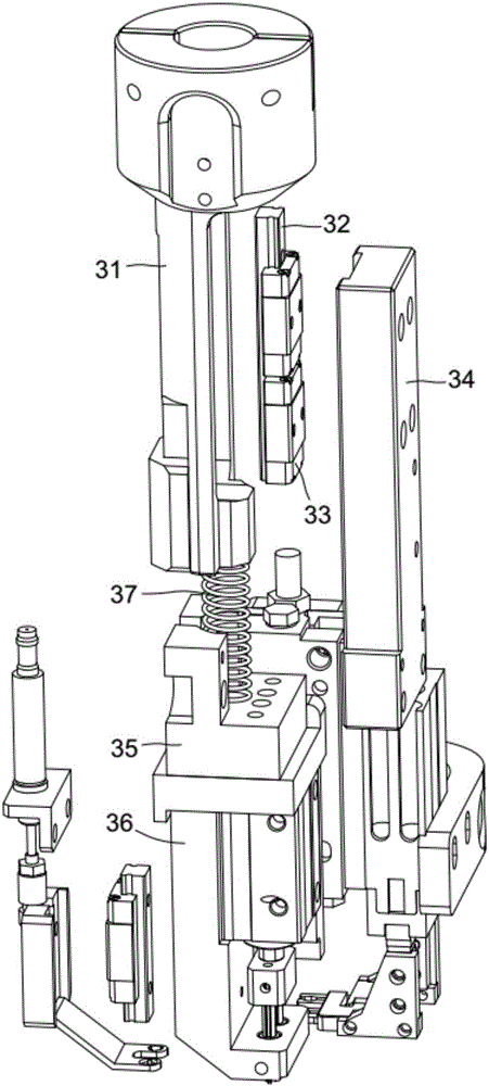
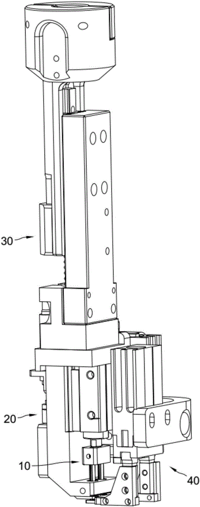
[0033] combine figure 1 , image 3 , Figure 4 , Figure 5 , Figure 7 , Figure 9 , Figure 10 , a jaw device for O-ring assembly, including a connecting module 30 connected to the motion module, a retrieving module 10 installed on the connecting module, a sleeve module 20 and a clamping module 40, the retrieving module is located in the connecting module Directly below the , the nesting module and the gripping module are located on both sides of the reclaiming module. The retrieving module includes a fixed and elastic retrieving sleeve 11, a retrieving needle 12 inserted in the retrieving sleeve that can be raised and lowered, and the retrieving needle is a pointed object with a small bottom and a large top. Comprising a liftable sleeve 21, the sleeve is provided with a through hole 210 that is matched with the material taking cover. The clamping module includes a liftable jaw cylinder 41, which can push up the O-ring on the pick-up sleeve 11. The lower part of the oute...


PUM


Abstract

The invention relates to a clamping claw device for assembling an O-shaped ring. The clamping claw device comprises a material taking module linked with a movement module, a sleeving module and a clamping module. The sleeving module and the clamping module are located on the two sides of the material taking module. The material taking module comprises a material taking sleeve which is fixedly arranged and has elasticity, and a material taking needle inserted in the material taking sleeve. The sleeving module comprises a sleeve head which is provided with a through hole matched with the material taking sleeve. The clamping module comprises a clamping claw air cylinder. During operation, after the material taking sleeve takes the O-shaped ring in a sleeving manner, the material taking needle moves downwards to stretch the material taking sleeve open so as to expand the O-shaped ring. The ascending clamping claw air cylinder strokes the O-shaped ring upwards along the material taking sleeve. A movement module drives the whole clamping claw device to move to the part above a product, the material taking needle moves upwards to reset, and the sleeve head moves downwards to upwards stroke the O-shaped ring to a cylinder on the surface of the product from the material taking sleeve. By means of the clamping claw device for assembling the O-shaped ring, the function of integrally assembling the O-shaped ring is achieved, automatic material taking is achieved, the O-shaped ring is not damaged, and the clamping claw device adapts to various specifications of O-shaped rings; and the overall structure is small and exquisite, and installation is fast.

Description

technical field [0001] The invention relates to O-ring installation equipment, in particular to a jaw device for O-ring assembly. Background technique [0002] The O-ring is set on the product by hand or with the help of tools, not only the operation efficiency is low, but also, the O-ring is forcibly stretched during the setting process, which is easy to be damaged. The invention patent application with the application number 201510853903.9 discloses an O-ring misalignment assembly device, which includes a misalignment traverse mechanism and a transport mechanism. The traverse mechanism includes a bottom plate, and a vertical plate is vertically connected to the rear of the bottom plate. , the slide rail is equipped with a traverse device; the conveying mechanism includes a supporting frame, the upper part of the supporting frame is provided with a horizontal plate, the upper and lower parts of the right side of the horizontal plate are provided with slideways, and the slid...

Claims


Application Information

Patent Timeline
IPC IPC(8): B23P19/00B23P19/027
CPCB23P19/003B23P19/027
Inventor 吕绍林马金勇朱晓锋张盼良占枝武金林根黎江岳
Owner BOZHON PRECISION IND TECH CO LTD
Why Eureka
Try Eureka