Multifunctional printing machine

A printing machine and multi-functional technology, which is applied in the field of multi-functional printing machines, can solve the problems of unsatisfactory PCB board printing and transportation difficulties, achieve the effect of convenient printing of PCB board through holes, improve production quality, and solve the effect of printing process

Inactive Publication Date: 2016-07-27
东莞市创威自动化科技有限公司
View PDF5 Cites 5 Cited by
  • Summary
  • Abstract
  • Description
  • Claims
  • Application Information

AI Technical Summary

Problems solved by technology

[0002] At present, the existing PCB board printing machine controls the actions of the alignment device, the scraper device and the adjustment device through the control program, so that the product can be printed accurately after entering the PCB board printing machine. However, due to the rapid development of current technology, The scope of use of PCB boards is also increasing, and the types and types of PCB boards are

Method used


Image

  • Multifunctional printing machine
  • Multifunctional printing machine
  • Multifunctional printing machine

Examples


Embodiment 1

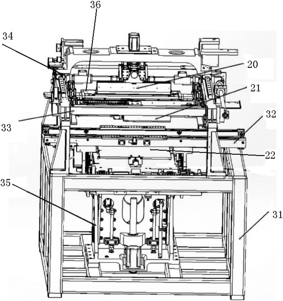
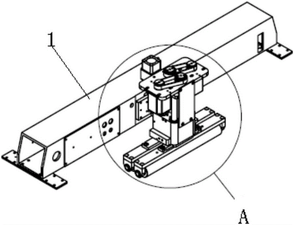
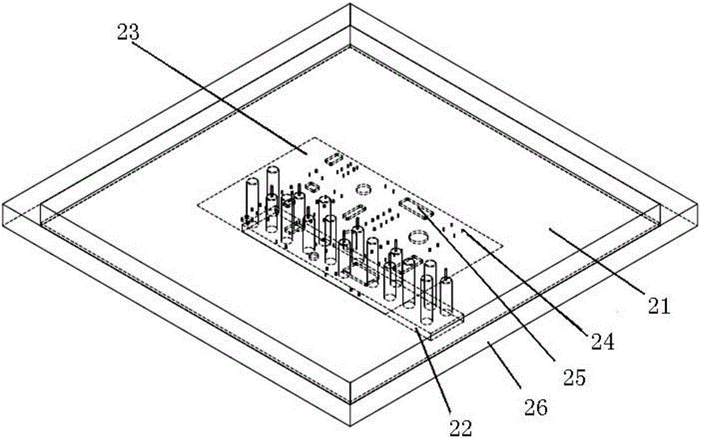
[0034] Embodiment one: if figure 1 , figure 2 , image 3 , Figure 4 and Figure 5 As shown, a multifunctional printing machine includes a frame 31, which is provided with an adjustable conveying track device 32 for conveying products and can adjust the height position according to the thickness of the product, and the adjustable conveying track device 32 is directly above A steel mesh moving device 33 is provided, and a scraper moving control device 34 is arranged directly above the steel mesh moving device 33. The steel mesh moving device 33 controls a steel mesh 21 with a middle groove, and the scraper moving control device 34 controls a flexible scraper Just below the head 20, the adjustable conveying track device 32 is provided with a product lifting device 35 that jacks up the products on the adjustable conveying track device 32. The product lifting device 35 is provided with a top PING structure 22, and the adjustable conveying track device 32 After the product is ...

Embodiment 2

[0062]Embodiment 2: A kind of multifunctional printing machine, comprises frame 31, is provided with on the frame 31 and is used for conveying product, and can adjust the height position according to product thickness adjustable conveying track device 32, the front and right sides of adjustable conveying track device 32 A steel mesh moving device 33 is provided above, and a scraper moving control device 34 is arranged directly above the steel mesh moving device 33. The steel mesh moving device 33 controls a flat steel mesh 21, and the scraper moving control device 34 controls a rigid scraper head. , just below the adjustable conveying track device 32 is provided with a product lifting device 35 that will jack up the product on the adjustable conveying track device 32, and a top PING structure 22 is provided on the product lifting device 35, and the adjustable conveying track device 32 After the product is transported from the adjustable conveying track device 32 to the designat...


PUM

PropertyMeasurementUnit
Depthaaaaaaaaaa
Apertureaaaaaaaaaa

Abstract

The invention discloses a multifunctional printing machine. The multifunctional printing machine comprises a machine frame. An adjustable conveying rail device which is used for conveying products is arranged on the machine frame, and the vertical position of the adjustable conveying rail device can be adjusted according to the thickness of the products. A steel mesh movement device is arranged over the adjustable conveying rail device. A scraper movement control device is arranged over the steel mesh movement device. The steel mesh movement device is used for controlling a steel mesh. The scraper movement control device is used for controlling a rigid or flexible scraper bit. A product lifting device is arranged under the adjustable conveying rail device. A top PING structure is arranged on the product lifting device. The steel mesh movement device, the adjustable conveying rail device, the scraper movement control device, the product lifting device and the scraper bit are all controlled by a control device. The control device is provided with two control systems. Free switching between the two control systems is achieved through a switching button. The two control systems include the PCB printing control system and the SMT board printing control system. When the PCB printing control system is in use, the scraper bit is flexible; and when the SMT board printing control system is in use, the scraper bit is rigid.

Description

technical field [0001] The invention relates to printing equipment, in particular to a multifunctional printing machine. Background technique [0002] At present, the existing PCB board printing machine controls the actions of the alignment device, the scraper device and the adjustment device through the control program, so that the product can be printed accurately after entering the PCB board printing machine. However, due to the rapid development of current technology, The scope of use of PCB boards is also increasing, and the types and types of PCB boards are also constantly changing, especially the size of PCB boards. Now most of the PCB boards used in digital technology products are small in size. It is difficult to use a traditional squeegee to scrape the solder paste onto the PCB, and the traditional stencil cannot meet the printing requirements of the PCB. Therefore, it is necessary to improve the stencil part and the scraper part of the printing machine. Contents...

Claims


Application Information

Patent Timeline
IPC IPC(8): B41F15/08B41F15/14B41F15/44B41F33/00
CPCB41F15/08B41F15/14B41F15/44B41F33/00
Inventor 王军涛苏金财贾夫振冼志军
Owner 东莞市创威自动化科技有限公司
Why Eureka
Try Eureka