Fluid control device

A technology for controlling equipment and fluids, which is applied in the direction of mechanical equipment, engine control, fuel air intake, etc., can solve the problem of small working range, achieve the effect of ensuring reliability and optimizing combustion function

Inactive Publication Date: 2016-07-27
MANN HUMMEL GMBH
View PDF7 Cites 0 Cited by
  • Summary
  • Abstract
  • Description
  • Claims
  • Application Information

AI Technical Summary

Problems solved by technology

Optimizes engine performance at specific engine speeds with a fixed-length charge air duct, but over a limited operating range

Method used


Image

  • Fluid control device
  • Fluid control device
  • Fluid control device

Examples


Embodiment Construction

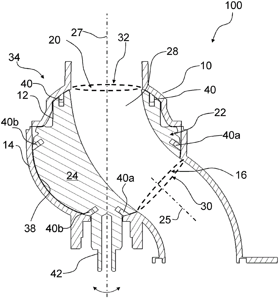
[0037] In the figures, the same reference numerals denote similar elements. The drawings are merely schematic diagrams, not intended to portray specific parameters of the invention. Moreover, the drawings are intended to depict only typical embodiments of the invention and therefore should not be considered as limiting the scope of the invention.

[0038] figure 1 A first example embodiment of a fluid control device 100 according to the present invention is depicted in a cross-sectional view in a first position of the valve body 24 of the control device 22, in which position the opening from the first port 20 to the second port 20 is open. The fluid path 28 of the second port 16 . figure 1 A fluid control device 100 (such as an air intake converter) in a fluid control device includes a housing 10 having a first port 20 and having a second port 16, the first port 20 having a first main axis perpendicular to the cross-section of the first port 20 27 , the second port 16 has a...


PUM


Abstract

The invention relates to a fluid control device, in particular an air intake shifter, which comprises a housing with one first port having a first main axis perpendicular to the cross section of the first port and with at least one second port having at least one second main axis perpendicular to the cross section of the at least one second port. The first main axis and the at least one second main axis are aligned off-axis to one another. A control means is arranged within the housing to control a fluid flow between the first port and the at least one second port. The control means comprises a valve body being rotatable around the first main axis of the first port, whereas the valve body comprises a fluid path for guiding the fluid through the valve body.

Description

technical field [0001] The present invention relates to a fluid control device, in particular to an air intake converter for an air duct of an internal combustion engine of a vehicle, and more particularly to a turbocharged engine such as a single-stage turbocharged engine) charge air duct. Background technique [0002] Within the meaning of the present invention, charge air is to be understood as compressed air compressed by an exhaust-gas turbocharger or other types of superchargers or compressors. [0003] For turbocharged engines, the geometry (diameter and length) of the charge air duct (also known as the charge air delivery duct) is tuned to benefit from the pressure waves used to improve the air filling in the engine cylinders and thereby increase output torque. [0004] However, the optimal geometry of the charge air duct depends on the engine speed. When the engine speed is high, say above 1500rpm (revolutions per minute) or so, and the load is also high, the tur...

Claims


Application Information

Patent Timeline
Patent Type & Authority Applications(China)
IPC IPC(8): F02B27/02F02M35/10F02D9/10
CPCF02B27/0278F02D9/101F02D9/103F02D9/104F02D9/1095F02M35/10065F02M35/10255F16K11/0876F02B37/162Y02T10/12
Inventor V.兰博J.米戈J.塞谢C.弗热勒T.格朗丹
Owner MANN HUMMEL GMBH
Why Eureka
Try Eureka