
A renewable energy utilization system

A renewable energy and user-friendly technology, applied in supercritical carbon dioxide systems, oxygen preparation, supercritical carbon dioxide preparation systems and transportation pipes, can solve the problems of difficult storage of electric energy, unstable energy supply, etc., to reduce emissions and improve Thermal efficiency, the effect of realizing effective utilization

Active Publication Date: 2019-06-04
SHIJIAZHUANG XINHUA IND FURNACE CO LTD
View PDF6 Cites 0 Cited by
  • Summary
  • Abstract
  • Description
  • Claims
  • Application Information

AI Technical Summary

Problems solved by technology

In addition, although renewable energy sources such as wind energy, solar energy, and tidal energy are cheap and clean, they are easily affected by natural conditions and the energy supply is unstable, and the generated electric energy is also difficult to store. The use of oxygen production systems and supercritical carbon dioxide production systems can Better storage and transport of renewable energy in the form of oxygen and supercritical carbon dioxide

Method used


Image

  • A renewable energy utilization system
  • A renewable energy utilization system
  • A renewable energy utilization system

Examples


Embodiment 1

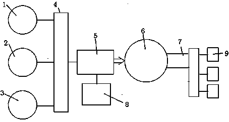
[0017] The renewable energy utilization system of the present invention is as figure 1 As shown, it includes a wind power generation unit 1 , a solar power generation unit 2 , a tidal power generation unit 3 , a substation 4 , an air separation oxygen generator 5 , an oxygen storage tank 6 , a nitrogen storage tank 8 , an oxygen delivery pipe 7 and an oxygen user 9 . The wind power generation unit, the solar power generation unit and the tidal power generation unit are respectively connected to the circuit of the substation, and the substation is connected to the circuit of the air separation oxygen generator. The system is provided with an oxygen unit or / and a supercritical carbon dioxide unit, and the air separation oxygen generator is connected with an oxygen storage tank and a nitrogen storage tank, and the oxygen storage tank is connected to an end oxygen user through an oxygen delivery pipe.

[0018] The electricity generated by wind energy, solar energy and tidal energy...

Embodiment 2

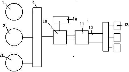
[0020] Another embodiment of the present invention is as figure 2 As shown, it includes a wind power generation unit 1, a solar power generation unit 2, a tidal power generation unit 3, a substation 4, a compressor 10, a supercritical carbon dioxide storage tank 11, a supercritical carbon dioxide pipe 12 and a supercritical carbon dioxide user 13. The wind power generation unit, the solar power generation unit and the tidal power generation unit are respectively connected to the substation circuit, and the substation is connected to the compressor circuit. The carbon dioxide storage tank 14 is connected with the compressor to provide a carbon dioxide source for the compressor to compress supercritical carbon dioxide. The compressor is connected to a supercritical carbon dioxide storage tank, and the supercritical carbon dioxide storage tank is connected to a supercritical carbon dioxide user through a supercritical carbon dioxide pipe.

[0021] The electricity generated by w...

Embodiment 3

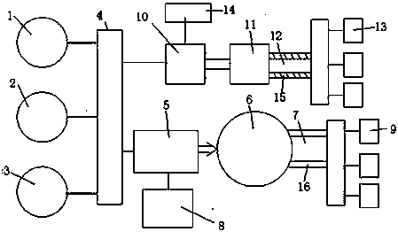
[0023] The third embodiment of the present invention is as image 3 As shown, it includes a wind power generation unit 1, a solar power generation unit 2, a tidal power generation unit 3, a substation 4, an air separation oxygen generator 5, an oxygen unit and a supercritical carbon dioxide unit. The oxygen unit includes an oxygen storage tank 6 , a nitrogen storage tank 8 , an oxygen delivery pipe 7 and an oxygen user 9 . The supercritical carbon dioxide unit includes a compressor 10 , a supercritical carbon dioxide storage tank 11 , a supercritical carbon dioxide pipe 12 and a supercritical carbon dioxide user 13 . The oxygen unit and the supercritical carbon dioxide unit are horizontally connected to the substation circuit. The outside of the oxygen delivery pipe is provided with a carbon dioxide protective gas sleeve 16, the oxygen channel is located in the center of the sleeve, and the carbon dioxide at normal temperature and pressure is located around the oxygen channel...


PUM


Abstract

The invention relates to a renewable energy resource utilization system. The renewable energy resource utilization system comprises a wind power generation unit, a solar power generation unit, a tidal power generation unit, a transformer substation, an oxygen unit, a supercritical carbon dioxide unit and an oxygen and supercritical carbon dioxide storing and conveying unit. The wind power generation unit, the solar power generation unit and the tidal power generation unit are connected with the transformer substation. The transformer substation is connected with the oxygen unit or / and the supercritical carbon dioxide unit through a circuit. The oxygen unit is provided with an air-separation oxygen generation device, an oxygen storage tank, a nitrogen storage tank and an oxygen conveying pipe. The supercritical carbon dioxide unit is provided with a compressor, a supercritical carbon dioxide storage tank, a supercritical carbon dioxide carbon and supercritical carbon dioxide users. According to the renewable energy resource utilization system, an electric generator is driven to generate electricity through wind energy, solar energy, tidal energy and the like, the generated electricity is used for preparing oxygen and preparing supercritical carbon dioxide through compression, effective utilization of green energy is achieved, the thermal efficiency of industrial heating is improved, and the nitrogen oxide emission is reduced.

Description

technical field [0001] The invention belongs to the technical field of new energy utilization, and relates to a system and a transport pipe for producing oxygen and supercritical carbon dioxide by utilizing renewable energy. [0002] It is mainly aimed at high energy consumption enterprises such as industrial kiln users. It relates to an oxygen production system using renewable energy, a supercritical carbon dioxide preparation system and a transportation pipeline network, and specifically relates to a system for preparing oxygen and supercritical carbon dioxide by using wind energy, solar energy and tidal energy. Background technique [0003] At present, the source of air pollution is mainly produced by exhaust emissions from industrial kilns, mainly concentrated in the production of industrial kilns in high energy-consuming enterprises such as power plants and cement plants. If all the combustion air of industrial kilns is replaced by pure oxygen, the content of nitrogen ...

Claims


Application Information

Patent Timeline
Patent Type & Authority Patents(China)
IPC IPC(8): F03B13/26F03D9/25F03G6/00F17D1/02F17C7/00F17D3/01C01B13/02
CPCC01B13/0248F03B13/26F03G6/00F17C7/00F17C2221/011F17C2221/013F17C2223/0123F17C2225/0123F17C2270/05F17C2270/0581F17D1/02F17D3/01Y02E10/30Y02E10/46Y02E10/72Y02P20/133Y02P20/54Y02P80/20
Inventor 贾会平
Owner SHIJIAZHUANG XINHUA IND FURNACE CO LTD
Learn More