Eureka AIR delivers breakthrough ideas for toughest innovation challenges, trusted by R&D personnel around the world.

Ultra-thin glass density testing device and testing method

An ultra-thin glass and testing device technology, which is applied in measuring devices, specific gravity measurement, instruments, etc., can solve problems such as large error range, weighing error, density test result error, etc., to improve measurement accuracy, reduce test errors, Fast test results

Inactive Publication Date: 2016-07-27
ZHENGZHOU XUFEI OPTOELECTRONICS TECH
View PDF6 Cites 13 Cited by
  • Summary
  • Abstract
  • Description
  • Claims
  • Application Information

AI Technical Summary

Problems solved by technology

Whether these previous test devices use a single metal rod connected suspension plate or a double metal chain connected tray, when measuring the wet weight of the sample, they cannot well correct the center of gravity deviation of the suspension plate and the sample caused by each time the sample is placed. The resulting weighing error has little effect on thick glass samples, but for thin glass, especially sheet glass with a thickness of less than 0.5mm, due to the light weight of the sample itself, the impact of the error will be magnified, resulting in density The test result has a large error
At the same time, when measuring the wet weight of glass, when air bubbles are attached to the surface of the sample, the sample needs to be taken out for re-testing. When taking and placing the sample again, it will also touch the suspension plate and cause the balance reading to fluctuate, causing weighing errors and prolonging the measurement. measurement time
For a thickness of 0.45mm, the density is 2.4g / cm 3 The flake glass has been tested and compared for many times, and it is found that the measurement error of the previous density test device can reach ±0.0025g / cm 3 , the error range is relatively large, which can no longer meet the needs of monitoring the stability of glass in the production line

Method used


Image

  • Ultra-thin glass density testing device and testing method
  • Ultra-thin glass density testing device and testing method
  • Ultra-thin glass density testing device and testing method

Examples


Embodiment Construction

[0022] The present invention will be described in further detail below in conjunction with the accompanying drawings and specific embodiments.

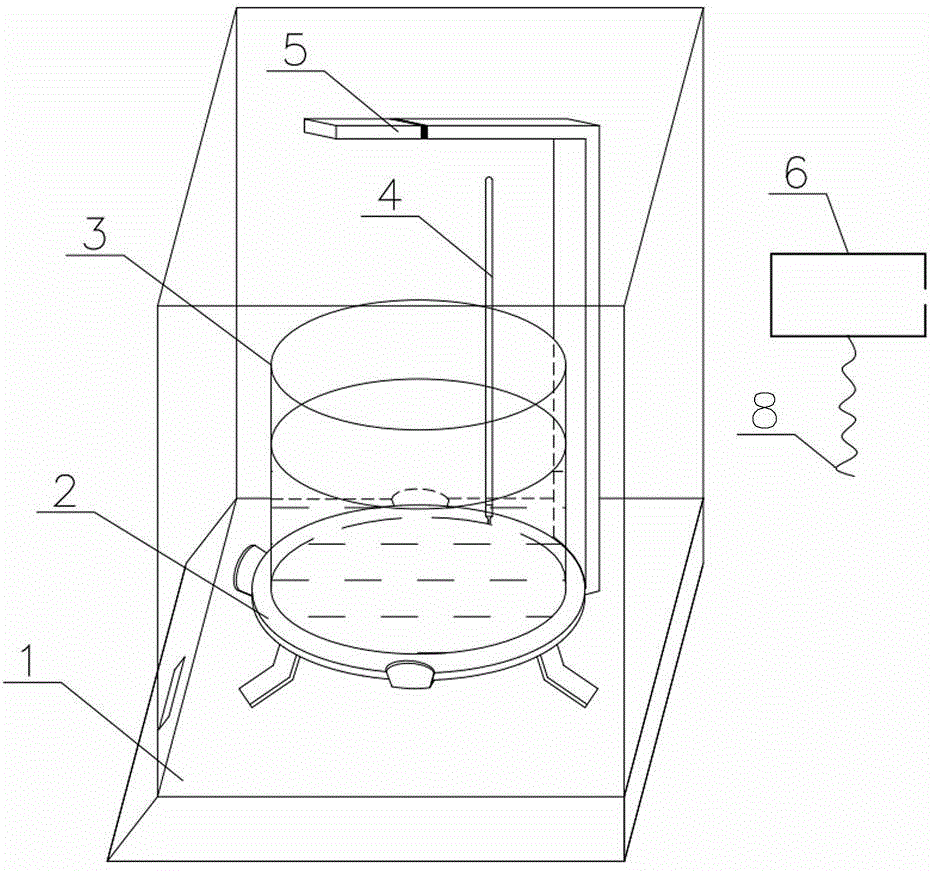
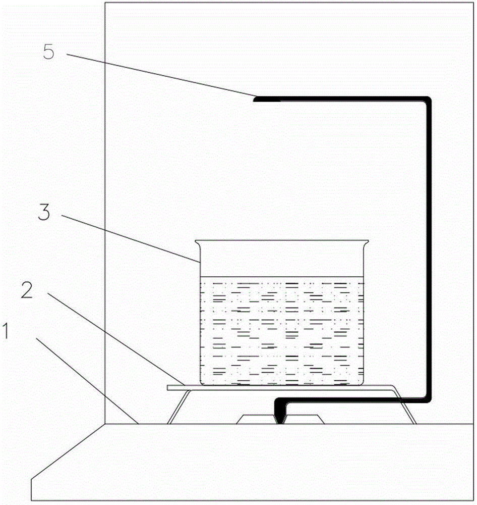
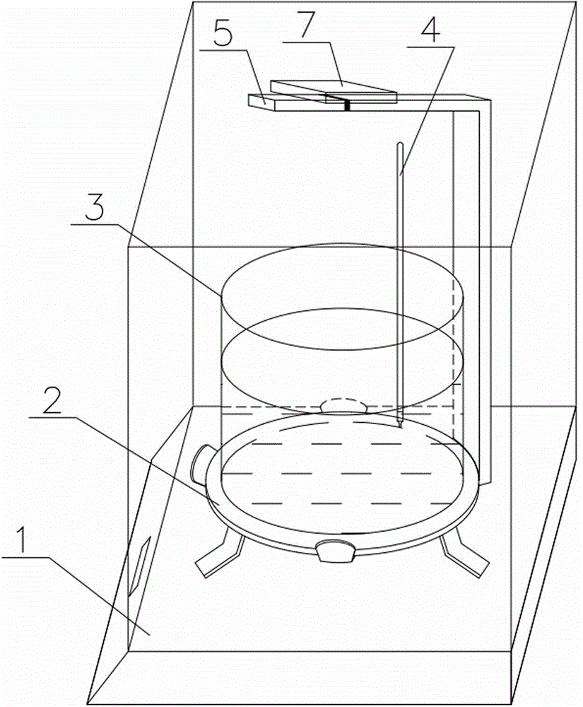
[0023] see figure 1 and figure 2 . The invention provides a device for testing the density of ultra-thin glass, comprising an electronic balance 1, on which a beaker support 2 and a weighing pan bracket 5 for placing a glass sample 7 are arranged, a beaker 3 is arranged on the beaker support 2, and the weighing pan The upper end of bracket 5 is positioned at the top of beaker 3; Thermometer 4 is set on beaker 3 inwalls; Described testing device also comprises pendant 6 and sling 8; Described pendant 6 is hung on the upper end of weighing pan carriage 5, and One end of the sling 8 is tied to the pendant 6, and the other end is provided with a slipknot for fixing the glass sample 7.

[0024] The pendant 6 should be selected from lightweight non-deformable materials, preferably metal wires and plastics.

[0025] In order to make the...


PUM


Abstract

The invention relates to a device for testing the density of ultra-thin glass, comprising an electronic balance, on which a beaker support and a weighing pan bracket for placing glass samples are arranged, a beaker is set on the beaker bracket, and the upper end of the weighing pan bracket is located above the beaker A thermometer is set on the inner wall of the beaker; the test device also includes a pendant and a sling; the pendant is hung on the upper end of the weighing pan bracket, one end of the sling is tied to the pendant, and the other end is provided with a slipknot for fixing the glass sample. The invention also includes a method for testing the density of ultra-thin glass using the device. Through the self-made pendant and hanging rope lamp test accessories, the present invention makes up for the deficiency of the existing density testing device in testing the density of thin glass sheets with a thickness less than 0.5mm, greatly reduces the test error, and provides a very practical device for thin glass testing. And the accessories are simple to make and convenient to obtain materials.

Description

technical field [0001] The invention belongs to the field of detection in the glass industry, and relates to a testing device and a measuring method for the density of ultra-thin glass. Background technique [0002] Density is an important physical property index of glass products. Density testing is usually used as a daily inspection in production to monitor the stability of glass products. At present, the general method of density testing in the glass industry is the weighing method based on Archimedes' law. The testing device based on this principle usually includes analytical balances, beakers, thermometers, hanging pans, trays and other accessories. Whether these previous test devices use a single metal rod connected suspension plate or a double metal chain connected tray, when measuring the wet weight of the sample, they cannot well correct the center of gravity deviation of the suspension plate and the sample caused by each time the sample is placed. The resulting we...

Claims


Application Information

Patent Timeline
IPC IPC(8): G01N9/00
Inventor 王俊明闫雪锋刘文渊李福庆关婧
Owner ZHENGZHOU XUFEI OPTOELECTRONICS TECH
Why Eureka
Eureka Blog
Learn More