Portable experimental power source device
A test power supply, portable technology, applied in the direction of circuit devices, battery circuit devices, current collectors, etc., can solve the problems of no circuit protection, etc., to prevent electric shock, improve the safety environment of electricity use, and facilitate the protection of electrical appliances
- Summary
- Abstract
- Description
- Claims
- Application Information
AI Technical Summary
Problems solved by technology
Method used
Image
Examples
Embodiment 1
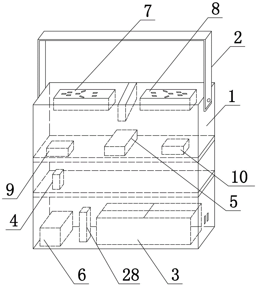
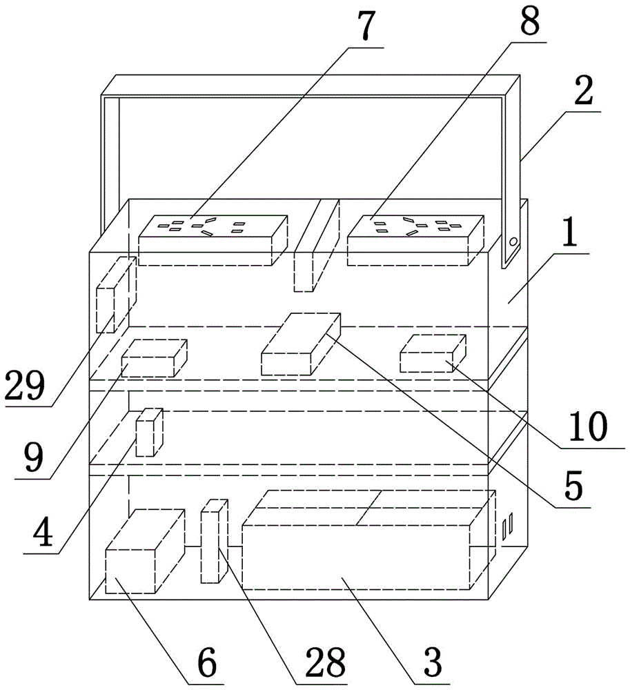
[0034] Such as figure 1 and figure 2 As shown, the present invention includes a casing 1, a handle 2 and a roller 31 fixed on the lower end surface of the casing 1 ( figure 1 and figure 2 Not shown, please refer to Figure 4 ), the rollers 31 are four and are universal wheels, the box body 1 is made of plastic insulating material, the two ends of the handle 2 are hinged on the left and right sides of the box body 1, and the box body 1 is fixedly connected to the power module 3, The inverter module 4, the transformer module 5, the control switch 6, the socket, the DC voltage stabilizing circuit 28 and the circuit breaker; the power module 3 is a 12V rechargeable DC battery, and the charging interface of the power module 3 extends to the outside of the box body 1; The inverter module 4 converts the 12V direct current into a 220V alternating current, and the transformer module 5 converts the 220V alternating current into a 110V alternating current; the control switch 6 is a ...
Embodiment 2
[0038] Such as Figure 3 to Figure 5 As shown, the present invention comprises box body 1, handle 2 and the roller 31 that is fixed on the lower end surface of box body 1, and roller 31 is four and is universal wheel, and box body 1 is made of plastic insulation material, and handle 2 The two ends are hinged on the left and right sides of the box body 1, and the box body 1 is fixedly connected with the power module 3, the inverter module 4, the transformer module 5, the control switch 6, the socket, the DC voltage stabilizing circuit 28, the circuit breaker and the cooling structure; The power module 3 is a 12V rechargeable DC battery, the charging interface of the power module 3 extends to the outside of the box body 1, the inverter module 4 converts 12V DC into 220V AC, and the transformer module 5 converts 220V AC into 110V AC, and the control The switch 6 is a leakage protection switch, the socket includes a socket 7 and a socket 2 8, the socket 7 and the socket 8 are fixe...
Embodiment 3
[0041] The structure of this embodiment is basically the same as the structure of Embodiment 2, the difference is: as Figure 6 to Figure 9 As shown, socket one 7 and socket two 8 all comprise base 17, sheet metal 18 and socket cover 19, and base 17 is cuboid structure, and sheet metal 18 is power supply contact, and socket cover 19 uses waterproof, insulating flexible material to make, Offer the socket 20 corresponding to sheet metal 18 on the base 17, the upper end face of cuboid structure and side end face are provided with slide rail 21, the slide rail 21 of socket one 7 side end faces is offered at left end face, the slide rail of socket two 8 side end faces Rail 21 is offered on the right side end face, and socket cover 19 is provided with the slide block 22 that cooperates with slide rail 21, and the right side end face of socket cover 19 is provided with clamping block 30, and clamping block 30 prevents socket cover 19 from sliding when vertical direction. The event of...
PUM
 Abstract
Description
Claims
Application Information
 - R&D
- Intellectual Property
- Life Sciences
- Materials
- Tech Scout
- Unparalleled Data Quality
- Higher Quality Content
- 60% Fewer Hallucinations
Browse by: Latest US Patents, China's latest patents, Technical Efficacy Thesaurus, Application Domain, Technology Topic, Popular Technical Reports.
© 2025 PatSnap. All rights reserved.Legal|Privacy policy|Modern Slavery Act Transparency Statement|Sitemap|About US| Contact US: help@patsnap.com


