Mine settling pond

A sedimentation tank and mine technology, applied in the field of mine shaft engineering research, can solve the problems of cumbersome manual cleaning, unsatisfactory results, slow sedimentation in mine sedimentation tanks, etc., and achieve good sedimentation effect

Inactive Publication Date: 2016-08-03
WUHAN DESIGN & RES INST OF CHINA COALTECH & ENG GROUP
View PDF3 Cites 0 Cited by
  • Summary
  • Abstract
  • Description
  • Claims
  • Application Information

AI Technical Summary

Problems solved by technology

[0004] Technical problem: In order to solve the problems of slow sedimentation, unsatisfactory effect, cumbersome manual cleaning and low effici

Method used


Image

  • Mine settling pond
  • Mine settling pond
  • Mine settling pond

Examples


Embodiment Construction

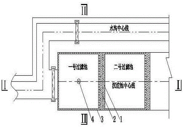
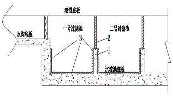
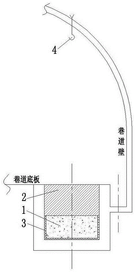
[0012] The present invention will be further described below in conjunction with the accompanying drawings.

[0013] The sedimentation tank that has been constructed is divided into several filter pools with a concrete retaining wall 1. The height of the retaining wall 1 is lower than the level of the bottom plate of the ditch. A stainless steel filter mesh 2 is installed on each retaining wall 1 to filter coal slime , and then use nylon monofilament mesh bag 3 to tile the bottom and surroundings of each filter tank, to ensure that the water in the ditch first flows into nylon monofilament mesh bag 3, and finally on the roadway wall directly above each nylon monofilament mesh bag 3 A suspension hook 4 is respectively set on the top. The water in the ditch enters the sedimentation tank and first settles in the No. 1 filter tank, and the sediment falls into the nylon monofilament mesh bag 3, and the water after the preliminary precipitation flows into the next filter tank after ...


PUM


Abstract

The invention discloses a mine sedimentation tank, which refers to separating the completed sedimentation tank into several filter pools with a concrete retaining wall, the height of the retaining wall is lower than the elevation of the bottom plate of the ditch, and a piece of stainless steel is installed on each retaining wall The filter mesh is used to filter the coal slime, and then the nylon monofilament mesh bag is tiled on the bottom and surroundings of each filter tank, and finally a hook is respectively set on the roadway wall directly above each nylon monofilament mesh bag. The invention has a good sedimentation effect, and adopts mechanical lifting to clean the sedimentation tank, instead of the traditional cleaning by manually lowering the tank.

Description

technical field [0001] The invention relates to a mine sedimentation tank, in particular to a new sedimentation tank with good sedimentation effect and easy cleaning. It belongs to the research field of mine shaft engineering. Background technique [0002] When the mine water flows to the water tank through the mining and excavation face and the long-distance roadway, it carries a large amount of coal and rock powder and other impurities. Before flowing to the water tank, a sedimentation tank is usually set up, and the mine water flows into the water after being settled in the sedimentation tank. The bin is discharged by the water pump. The sedimentation process of the traditional sedimentation tank is slow, and the mine water enters the water tank and the water suction well before it can fully settle, which will lead to increased wear of the flow-passing parts of the water pump and accelerate the damage of the water pump. At the same time, when the water suction well has t...

Claims


Application Information

Patent Timeline
IPC IPC(8): B01D36/04
CPCB01D36/04
Inventor 吴磊辛德林张建平张忠文贾成刚于新锋刘艳王颂华沈金山
Owner WUHAN DESIGN & RES INST OF CHINA COALTECH & ENG GROUP
Why Eureka
Try Eureka