Tire molding capsule device and preparation method thereof
A technology of tire molding and capsules, which is applied in the field of tire molding, and can solve problems such as the difference in the direction of the bonding force between the capsule rubber material and the anti-adhesive cloth, which cannot be guaranteed, and the quality of the capsule fluctuates.
- Summary
- Abstract
- Description
- Claims
- Application Information
AI Technical Summary
Problems solved by technology
Method used
Image
Examples
Embodiment 1
[0030] Example 1 Capsule
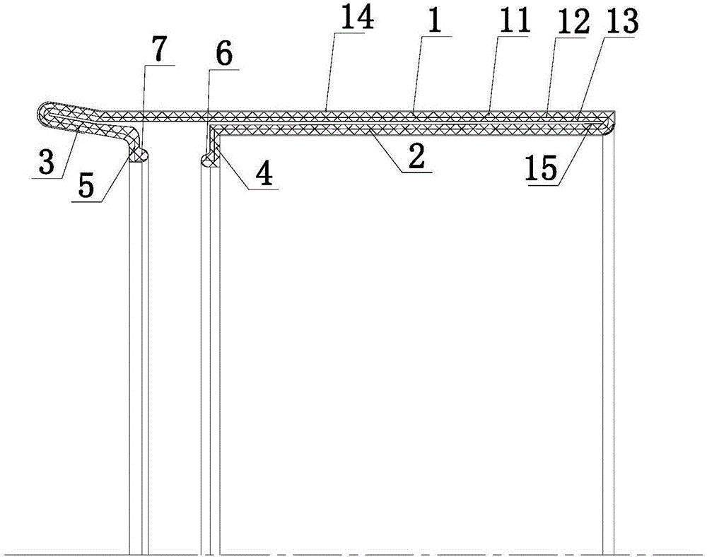
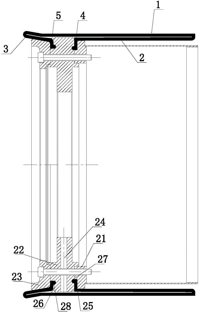
[0031] Such as figure 1 As shown in a tire building bladder device, the bladder includes an integrally vulcanized outer bladder 1, a first reverse bladder 2 and a second reverse bladder 3, the first reverse bladder 2 and the second reverse bladder The capsule body 3 is respectively connected to the two ends of the outer capsule body 1 and folded back and turned up. The capsule body is composed of an outer rubber layer 11, a reinforcing skeleton layer 12 and an inner rubber layer 13, and an anti-adhesive cloth 14 is arranged on the outer surface of the outer capsule body 1, and the two ends of the anti-adhesive cloth 14 are turned up to the first turned-up bag The inner surface of the body 2 and the second turned-back capsule body 3 , the outer capsule body 1 and the turn-back area of the first turned-back capsule body 2 are provided with a reinforcing glue layer 15 . The outer annular surface of the second anti-encapsulation body 3 is an oblique ...
Embodiment 2
[0032] Embodiment 2 molding die
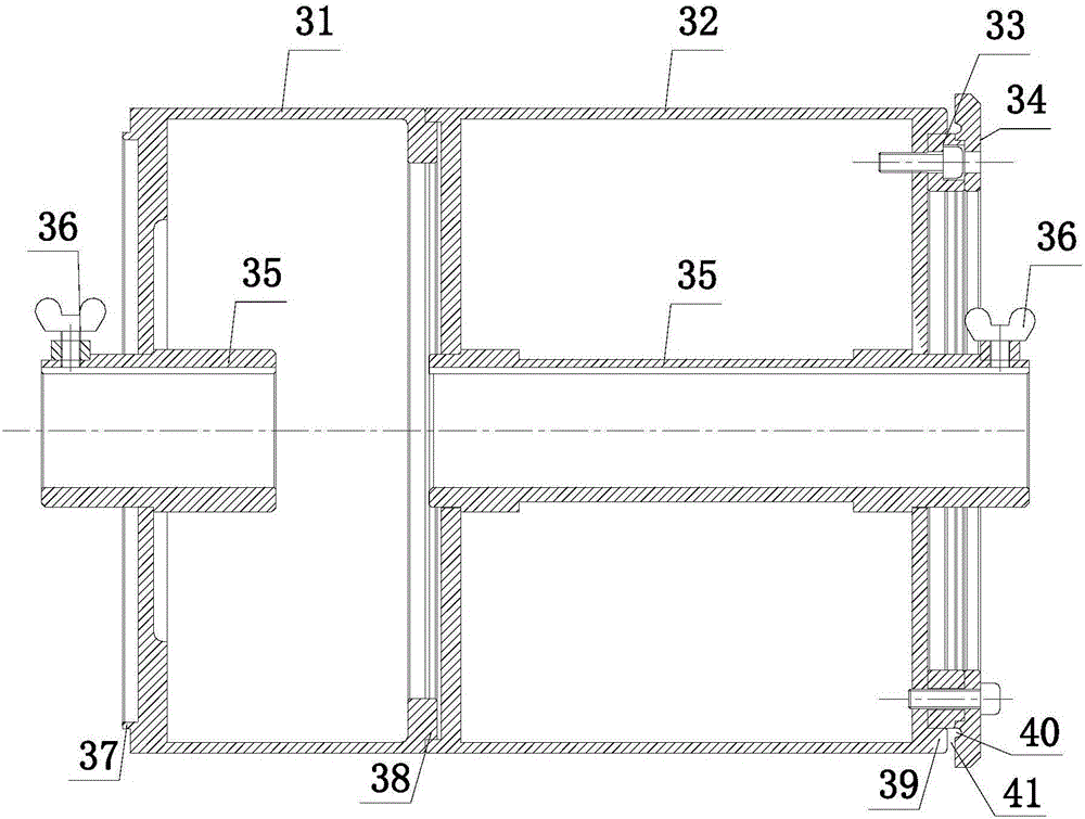
[0033] Such as image 3 The molding die shown includes a first bladder 31 , a second bladder 32 , a pressure ring 33 and a back cover 34 . A connecting sleeve 35 is connected between the first bladder 31 and the second bladder 32 , and the connecting sleeve 35 is used for connecting the rotating shaft. Fastening screws 36 are arranged on the connecting sleeve 35 . The left end of the first bag tube 31 is provided with the first slit convex ring 37, and the right end is provided with the connecting convex ring 38, and the first bag tube 31 and the second bag tube 32 are connected to each other by connecting the convex ring 38, and the second bag tube 32 right-hand ends are provided with the second sub-mouth protruding ring 39, and described pressing ring 33 is fixedly arranged in the annular groove that the second sub-mouth protruding ring 39 forms, and the outer ring of pressing ring 33 and the inner part of the second sub-mouth protruding ri...
Embodiment 3
[0034] Embodiment 3 vulcanization mold
[0035] Such as Figure 4 The vulcanization mold shown includes a first bladder 31 , a third bladder 42 , an external bladder 43 , a bottom cover 44 and an upper cover 45 . The first capsule 31 is the same as the first capsule 31 of Embodiment 1, the outer ring of the first capsule 31 is the first surface 46, the middle connection of the first capsule 31 is provided with a connecting sleeve 35, the connecting sleeve 35 is used to connect the rotating shaft, and a fastening screw 36 is arranged on the connecting sleeve 35 . The first sub-port protruding ring 37 on the left side of the first bag tube 31 is connected with the right side of the third bag tube 42, the outer ring of the third bag tube 42 is the second surface 47, and the right side end of the third bag tube 42 A first forming notch 48 is provided, and a first sub-mouth die 49 is formed between the third bladder 42 and the first sub-mouth protruding ring 37 . The left end of...
PUM
| Property | Measurement | Unit |
|---|---|---|
| thickness | aaaaa | aaaaa |
Abstract
Description
Claims
Application Information
 - R&D
- Intellectual Property
- Life Sciences
- Materials
- Tech Scout
- Unparalleled Data Quality
- Higher Quality Content
- 60% Fewer Hallucinations
Browse by: Latest US Patents, China's latest patents, Technical Efficacy Thesaurus, Application Domain, Technology Topic, Popular Technical Reports.
© 2025 PatSnap. All rights reserved.Legal|Privacy policy|Modern Slavery Act Transparency Statement|Sitemap|About US| Contact US: help@patsnap.com


