Rope gripper

A rope clamp and rope technology, which is applied in the field of rope clamps, can solve the problem that the safety brake cannot meet the actual use needs of elevator safety protection, and achieve reliable and fast pinch brake, realize safe brake, and realize the protection function Effect

Active Publication Date: 2016-08-03
SHIJIAZHUANG WULON BRAKE
View PDF11 Cites 12 Cited by
  • Summary
  • Abstract
  • Description
  • Claims
  • Application Information

AI Technical Summary

Problems solved by technology

[0008] The purpose of the present invention is to provide a rope clamp to solve the problem that the existing safety brake cannot meet the actual use needs of elevator safety protection

Method used


Image

  • Rope gripper
  • Rope gripper
  • Rope gripper

Examples


Embodiment 1

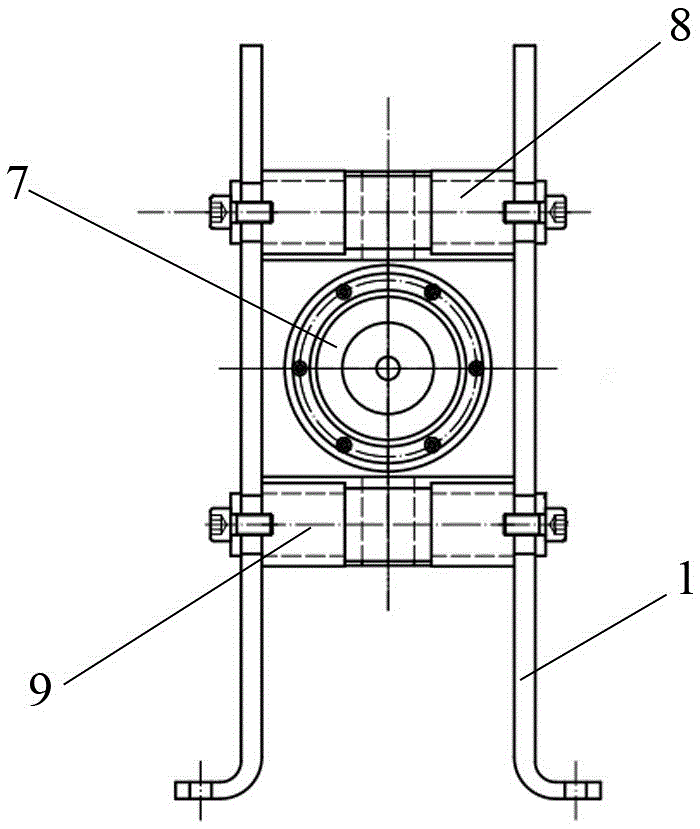
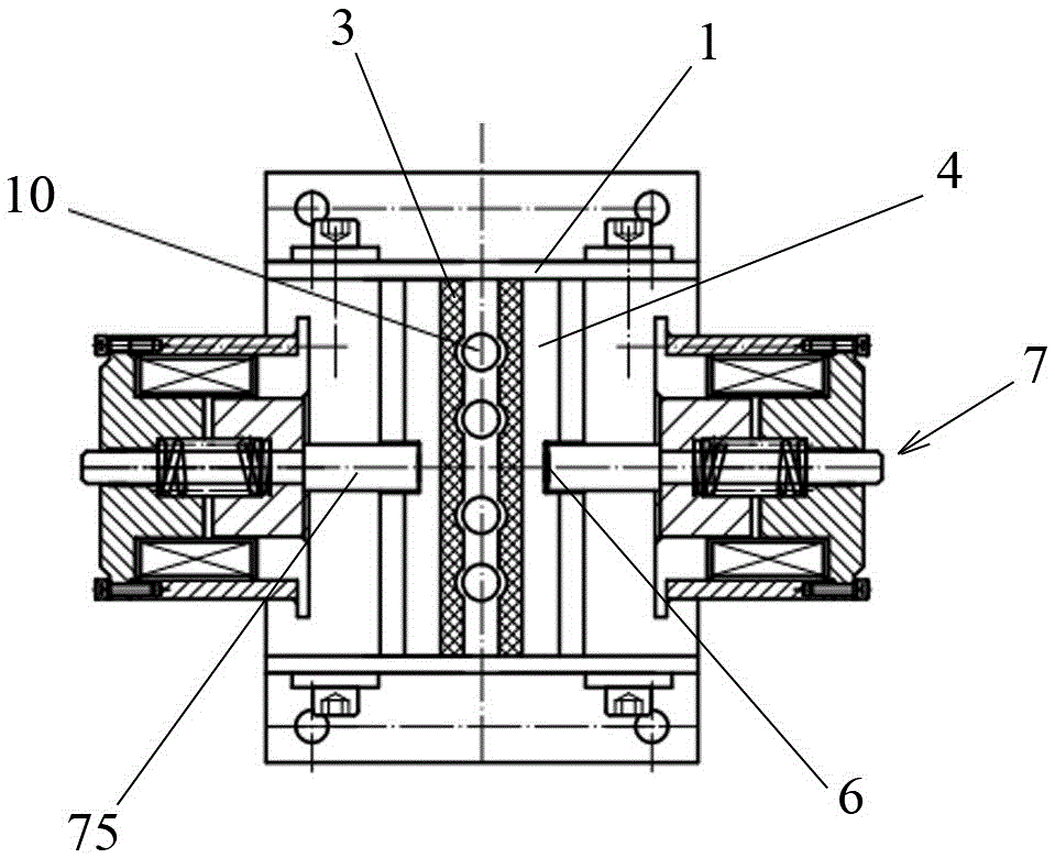
[0032] Such as figure 1 , figure 2 , image 3As shown, the frame 1 is a plate-frame three-dimensional structure surrounded by two end plates and two side frame plates, and two brake clips are arranged in the frame 1, and the clamping of the two brake clips A rope channel 2 is formed between the faces. Both brake clips are movable clips 4, and the structure of the two movable clips 4 is the same, and they are upright and symmetrically arranged in the frame 1 ( figure 1 ). The opposite surfaces of the two movable clamping blocks 4 are clamping surfaces, and the clamping surfaces of the two movable clamping blocks 4 are parallel to each other, and friction plates 3 are arranged on the clamping surfaces of each movable clamping block 4 . The gap between the clamping surfaces of the two movable clamping blocks 4 is the rope channel 2 for passing through the steel wire rope, and the steel wire rope 10 travels up and down in the frame 1 of the rope clamp ( image 3 ). figure 1...

Embodiment 2

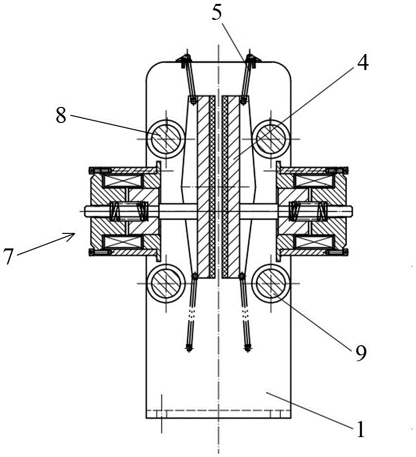
[0043] Such as Figure 5 As shown, the structure of this embodiment is basically the same as that of Embodiment 1, and the frame 1 is also equipped with double movable clamping blocks. Similarly, two brake trigger mechanisms are correspondingly installed on the frame 1 . The two brake triggering mechanisms all include a brake electromagnet 7, a compression spring 74, a brake push rod 75, etc., and the brake electromagnet 7 adopts an electromagnetic brake triggered by power failure. The front ends of the brake push rods 75 in the two brake trigger mechanisms respectively abut against the longitudinal chute 6 on the back side of the movable clamp block 4 on each side to perform the trigger operation of the safety brake.

[0044] The difference is that four upper horizontal shafts 8 and four lower horizontal shafts 9 are arranged on the frame 1, that is, two parallel horizontal shafts are arranged at each horizontal shaft setting position, and two parallel horizontal shafts are a...

Embodiment 3

[0046] Such as Figure 6 As shown, the basic structure of this embodiment is roughly the same as that of Embodiment 1, the main difference being the two brake clips arranged in the frame 1, one is the movable clip 4, and the other is the fixed clip 11 . The fixed clamping block 11 is fixedly installed in the frame 1, and there is no need to set a brake trigger mechanism to trigger and brake it. Therefore, in this embodiment, only the frame end plate on the side of the movable clamping block 4 is provided with The brake trigger mechanism applies a positive brake trigger extrusion force to the movable clamp block 4 .

[0047] In the present embodiment, the upper cross shaft 8 and the lower cross shaft 9 arranged on the frame 1 are a double-shaft arrangement structure as in embodiment 2, and the two cross shafts in each group are connected with the movable clamp block 4 The oblique position corresponding to the inclination of the slope is set to form a continuous limit to the m...


PUM


Abstract

The invention relates to a rope gripper. The rope gripper is structurally characterized in that two brake clamping blocks of which clamping surfaces are opposite to each other are arranged in a rack; at least one of the two brake clamping blocks is a movable clamping block; the back of each movable clamping block comprises an upper inclined plane and a lower inclined plane, so that the movable clamping block forms a compound wedge-shaped block formed by connecting an upper wedge-shaped body and a lower edge-shaped body; an elastic draw-off mechanism for drawing off the movable clamping blocks is arranged on the rack; upper transverse shafts and lower transverse shafts are arranged on the rack; an axial plane of each upper transverse shaft is opposite to an upper inclined plane of the back of the corresponding movable clamping block; an axial plane of each lower transverse shaft is opposite to a lower inclined plane of the back of the corresponding movable clamping block; and according to the setting positions of the upper transverse shafts and the lower transverse shafts, the movable clamping blocks can generate translation towards the direction of the clamping surface in the upward or downward moving process, so that a rope passing through a rope channel is clamped and stopped. The rope gripper disclosed by the invention serves as a safety brake; and a car or a hoisted heavy object can be immediately gripped by the rope gripper no matter upward heading or downward rolling, thereby preventing malignant consequence caused by unforeseen circumstances.

Description

technical field [0001] The invention relates to a rope brake, in particular to a rope clamp. Background technique [0002] In recent years, accidents of elevators slipping, rushing to the top, and squatting at the bottom have occurred from time to time. In order to curb the occurrence of such accidents, elevators have been added to the No. Mandatory requirements for safety protection devices to prevent accidental movement of the car should be added to prevent vicious casualties caused by accidental movement of the car. [0003] Existing safety protection devices to prevent accidental movement of the car generally include the following three methods: [0004] The first way is to add a separate set of brakes on the basis of the original brakes as a redundant design. The disadvantage of this form is that if the car unexpectedly moves in the power failure state, the two brakes will act at the same time, which not only greatly increases the original adjusted braking torque, but...

Claims


Application Information

Patent Timeline
Patent Type & Authority Applications(China)
IPC IPC(8): B66B5/24B66B5/16
CPCB66B5/16B66B5/24
Inventor 韩伍林郝雄毅
Owner SHIJIAZHUANG WULON BRAKE
Why Eureka
Try Eureka