Manufacture of sliding unloading device controlled by hydraulic displacement and method for unloading components

A technology of displacement control and unloading device, which is applied in building construction, processing of building materials, construction, etc., can solve problems such as unstable unloading, achieve the effects of avoiding welding process, convenient operation, and ensuring precise control

Active Publication Date: 2017-11-03
YUNNAN CONSTR INVESTMENT HLDG GRP CO LTD +1
View PDF9 Cites 0 Cited by
  • Summary
  • Abstract
  • Description
  • Claims
  • Application Information

AI Technical Summary

Problems solved by technology

The sand box unloading method has high requirements for sand particles. During the unloading process, the friction between sand particles and the friction between sand particles and the sand box may cause unstable unloading.

Method used


Image

  • Manufacture of sliding unloading device controlled by hydraulic displacement and method for unloading components
  • Manufacture of sliding unloading device controlled by hydraulic displacement and method for unloading components
  • Manufacture of sliding unloading device controlled by hydraulic displacement and method for unloading components

Examples


Embodiment Construction

[0018] The present invention will be further described below in conjunction with accompanying drawing.

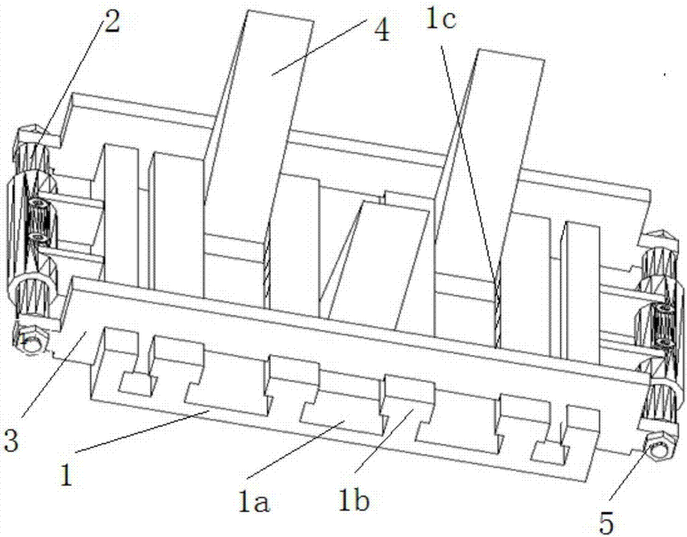
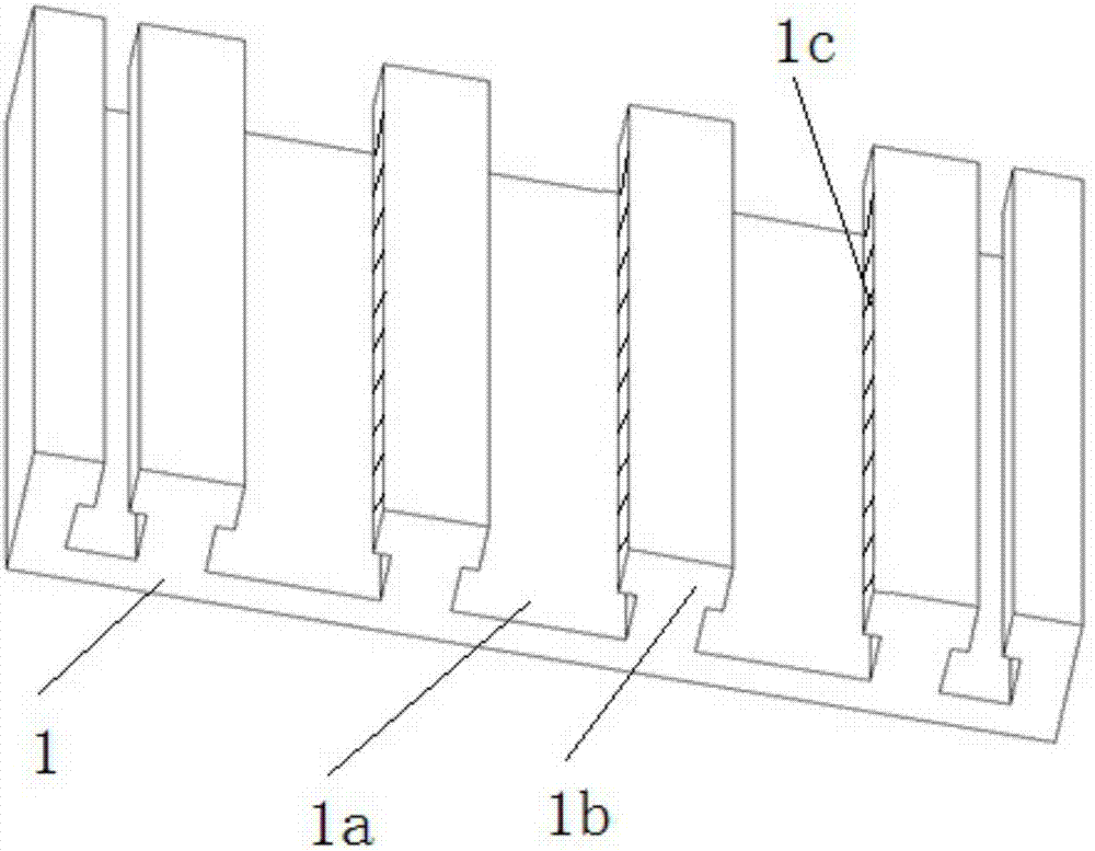
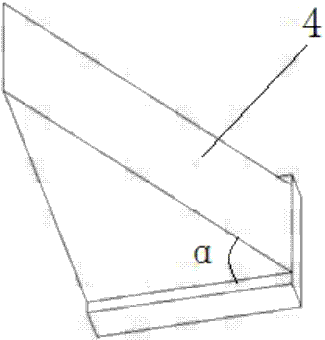
[0019] Such as Figure 1 to Figure 5 The sliding unloading device with hydraulic rod displacement control shown includes a rectangular support base 1 with a set of parallel chute 1a on the top surface, and two limiting hydraulic rods that are symmetrically installed on both sides of the support base and are parallel to the chute. 2. Two parallel baffles that are symmetrically installed on the other two sides of the support base and can slide along the chute 3. Right-angled triangular plates that are installed on the support base and are located in the two baffles and can slide along the chute 4; baffles The two ends of 3 are respectively set on the limit hydraulic rods 2 on both sides; a raised guide rail 1b is formed between the chutes; there are at least three right-angled triangles, of which two right-angled triangles are installed symmetrically at least one chute apart,...


PUM


Abstract

The invention relates to a hydraulic displacement control slip unloading device and a method for manufacturing and unloading a member. The unloading device comprises a rectangular supporting base (1), two limiting hydraulic rods (2), two baffles (3), and right-angled triangular plates (4), wherein a set of parallel sliding grooves (1a) is formed in the top face of the rectangular supporting base (1), the limiting hydraulic rods (2) are symmetrically installed at the two sides of the supporting base and parallel to the sliding grooves, the baffles (3) are symmetrically installed at the other two sides of the supporting base and are in parallel and capable of sliding along the sliding grooves, and the right-angled triangular plates (4) are installed on the supporting base and located between the two baffles and can slide along the sliding grooves. The two ends of each baffle are installed on the limiting hydraulic rods in a sleeving mode respectively, convex guide rails (1b) are formed between the sliding grooves, the number of the right-angled triangular plates is at least three, two right-angled triangular plates are symmetrically installed and at least spaced by one sliding groove, and the two right-angled edges are attached to the supporting base and the baffle at one side; the third right-angled triangular plate is located between the two right-angled triangular plates and installed oppositely, and the two right-angled edges are attached to the supporting base and the baffle at the other side. The unloading device is used for unloading of steel structure engineering and is easy to operate, high in stability and high in control precision.

Description

technical field [0001] The invention belongs to the technical field of construction engineering, and relates to a tool for unloading construction in the construction process of a steel structure. Background technique [0002] Steel structure engineering, especially the installation of large-span steel grid structures in space, often uses support frames to complete the construction. After the structure is installed, it forms a stable stress system with the support frames. Finally, the support frames need to be removed and the support frames are released. The load borne is transferred to be borne by the structure itself, and this construction step is unloading. At present, the commonly used methods for unloading structural support systems include screw jack unloading method, electronically controlled hydraulic jack unloading method, and sand box unloading method. For engineering projects with more supporting points, more jack equipment needs to be set, which increases the con...

Claims


Application Information

Patent Timeline
Patent Type & Authority Patents(China)
IPC IPC(8): E04G21/16
CPCE04G21/169
Inventor 王晓燕王剑非朱文伟张恩超魏聪明王建成
Owner YUNNAN CONSTR INVESTMENT HLDG GRP CO LTD
Why Eureka
Try Eureka