
Floor spring test system

A test system and frame technology, applied in the testing of mechanical parts, the testing of machine/structural parts, measuring devices, etc., can solve the problems of long time consumption, low precision, and large labor, saving time and labor, Improved accuracy and compact structure

Active Publication Date: 2016-08-03
佛山市质量计量监督检测中心 +1
View PDF10 Cites 6 Cited by
  • Summary
  • Abstract
  • Description
  • Claims
  • Application Information

AI Technical Summary

Problems solved by technology

In addition to life, other mechanical performance items are generally tested manually. There are problems such as heavy labor, long time consumption, and different test errors, which will eventually lead to uneven quality of products entering the market.
At present, the floor spring testing equipment on the market is mainly designed for the factory test of the floor spring, with a single function and low precision; in order to meet the needs of testing efficiency, multi-station testing should be done as much as possible, thereby reducing the size of the standard requirements

Method used


Image

  • Floor spring test system
  • Floor spring test system
  • Floor spring test system

Examples


Embodiment Construction

[0042] The technical solution of the present invention will be further described below in conjunction with the accompanying drawings and through specific implementation methods.

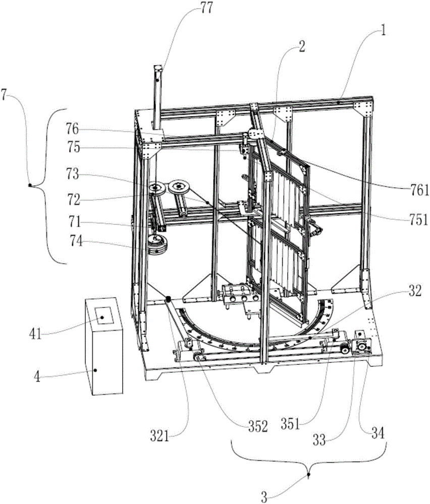
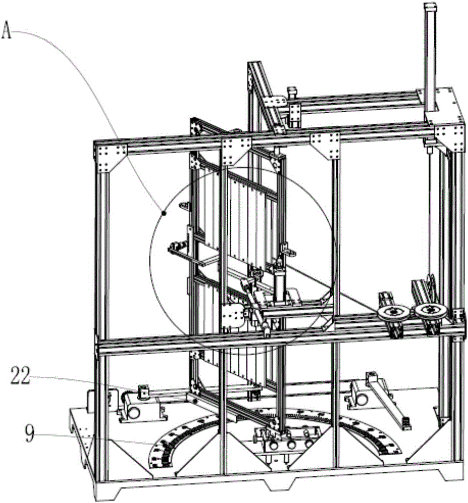
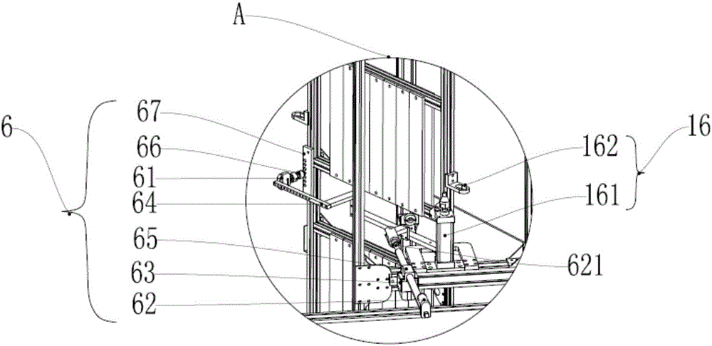
[0043] Such as figure 1 and figure 2 As shown, a floor spring test system includes a frame body 1, a test door 2, an actuator 3 and an electric control box 4;

[0044] The test door 2 is hinged in the frame 1 so that it can swing in the frame 1;

[0045] A swing groove 22 is installed at the bottom of the test door 2;

[0046] The actuator 3 is mounted on the bottom of the frame 1;

[0047] It also includes a swing rod 32, which is installed on the actuator 3, and the actuator 3 drives the swing rod 32 to rotate so as to cooperate with the swing groove 22 and pull the test door 2 to open and close;

[0048] It also includes a counting sensor installed on the frame body 1 .

[0049] The electric control box 4 is arranged on one side of the frame body 1 .

[0050] When using said a kind of groun...


PUM


Abstract

A floor spring test system comprises a frame body, a test door, an actuator, and an electric control box. The test door is hinged into the frame body and can swing in the frame body. The bottom of the test door is equipped with a swing slot. The actuator is mounted at the bottom of the frame body. The floor spring test system further comprises a swing rod which is mounted on the actuator. The actuator drives the swing rod to rotate and match the swing slot so as to pull the test door to be opened or closed. The floor spring test system further comprises a counting sensor which is mounted on the frame body. The electric control box is arranged at one side of the frame body. With the floor spring test system, the unidirectional life and bidirectional life of a floor spring can be measured. The floor spring test system accords with the test standard. The counting sensor is used for calculating the number of fatigue tests. The whole process is automated, the test precision is improved, and error caused by manual test is reduced.

Description

technical field [0001] The invention relates to the field of testing machinery, in particular to a floor spring testing system. Background technique [0002] The floor spring is a hydraulic door closer, which relies on the worm gear mechanism to realize the automatic closing of the door in both forward and reverse directions. With the widespread use of floor springs, the quality requirements for floor springs are getting higher and higher. According to industry standards, floor springs need to test mechanical items such as life closing time, closing torque, energy efficiency ratio, load performance, door opening buffer performance and delayed closing function. In addition to life, other mechanical performance items are generally tested manually. There are problems such as heavy labor, long time consumption, and different test errors, which will eventually lead to uneven quality of products entering the market. At present, the floor spring testing equipment on the market is...

Claims


Application Information

Patent Timeline
Patent Type & Authority Applications(China)
IPC IPC(8): G01M13/00
CPCG01M13/00
Inventor 任湘张娟徐有明骆剑辉
Owner 佛山市质量计量监督检测中心
Learn More