Metallographical low-temperature observation device

A low-temperature, room-temperature technology, applied in measuring devices, material analysis through optical means, instruments, etc., can solve problems such as inability to achieve observation and analysis, and difficult to meet the needs of sample material analysis, and achieve the effect of compact structure and convenient operation

Inactive Publication Date: 2016-08-03
TECHNICAL INST OF PHYSICS & CHEMISTRY - CHINESE ACAD OF SCI
7 Cites 1 Cited by

AI-Extracted Technical Summary

Problems solved by technology

[0003] In recent years, scientific research on materials has found that the deformation mechanism of the microstructure of materials at low temperature is significantly different from that at room temperature. In the current research on the low temperature characteristics of materials, the material is first treated at low temperature and then r...

Method used

Further, above-mentioned low temperature platform 4 is placed on cold capacity transport channel 3, does not directly contact with vacuum cover 1, cold capacity transport channel 3 provid...

Abstract

The invention discloses metallographical low-temperature observation device .The device comprises a cold delivery channel connected with a low-temperature cold head, a low-temperature platform used for carrying an observation sample, a vacuum cover used for containing the cold delivery channel and the low-temperature platform, and an observation window formed in the upper portion of the vacuum cover .A moving sliding block is placed on the low-temperature platform and can slide relative to the low-temperature platform, and the low-temperature platform and the moving sliding block are both connected and fixed to the observation sample .The device further comprises a tension-compression rod connected with the moving sliding block .By means of the device, tension and compression of the sample material under the low temperature condition can be observed; besides, the device is compact in structure and convenient to operate.

Application Domain

Preparing sample for investigationMaterial analysis by optical means

Technology Topic

EngineeringTension compression

Image

  • Metallographical low-temperature observation device
  • Metallographical low-temperature observation device

Examples

  • Experimental program(1)

Example Embodiment

[0019] In order to make the objectives, technical solutions, and advantages of the present invention clearer, the following will further describe the embodiments of the present invention in detail with reference to the accompanying drawings and specific embodiments. It should be understood that the specific embodiments described in this specification are only for explaining the present invention, not for limiting the present invention.
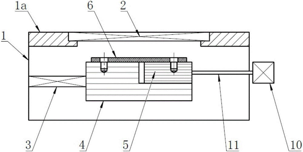
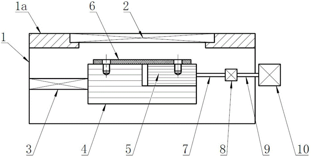
[0020] See figure 1 As shown, an embodiment of the present invention provides a cryogenic observation device, which includes a cold mass transport channel 3 connected to a cryogenic cold head (not shown), a cryogenic platform 4 on which an observation sample 6 is placed, and a housing The vacuum cover 1 of the cold transport channel 3 and the cryogenic platform 4 is provided with an observation window 2 above the vacuum cover 1. On the cryogenic platform 4 is placed a movable slider 5 that can slide relative to the cryogenic platform 4, and the cryogenic platform 4 and the movable slider 5 are all connected and fixed with the observation sample 6, and the above-mentioned device also includes a pulling and pressing rod 10 connected to the moving slider 5.
[0021] The vacuum cover 1 is a generally rectangular cavity structure, which provides a vacuum environment for metallographic low-temperature observation. The structure of the vacuum cover 1 can also be set to a different structure according to actual needs.
[0022] The upper and left sides of the vacuum cover 1 are provided with vacuum cover flanges 1a, the observation window 2 is placed on the above-mentioned vacuum cover flange 1a, and the material of the observation window 2 is quartz glass, which can also be made of other transparent materials as required.
[0023] The cold capacity transport channel 3 is a tubular arrangement, one end of which is connected with a low-temperature cold head. The cold source of the low-temperature cold head is a low-temperature refrigerator, or a low-temperature medium, such as liquid nitrogen, liquid helium, etc. The other end of the cold transport channel 3 is connected to the low temperature platform 4 to provide the required cold temperature for the low temperature platform 4.
[0024] Further, the above-mentioned low-temperature platform 4 is placed on the refrigerating transport channel 3, and is not in direct contact with the vacuum cover 1. The refrigerating transport channel 3 provides support for the low-temperature platform 4, which can effectively reduce the contact between the low-temperature platform 4 and other structures , Reducing the heat leakage of the low temperature platform 4.
[0025] The low-temperature platform 4 has a rectangular parallelepiped structure as a whole, and its upper right corner is provided with a vacant accommodating part (not marked). The accommodating part is provided with a movable sliding block 5 which can be opposed to the low-temperature platform 4 on the accommodating part. slide. The low temperature platform 4 has a temperature control function, and the temperature control range is from low temperature to room temperature, which can provide the required temperature for the observation sample 6.
[0026] The moving slider 5 has a rectangular parallelepiped structure, and its lower end is connected with the bottom end of the accommodating part of the low-temperature platform 4, and its right side is connected with a tension and compression rod 11, which can pull/push the aforementioned movable slider 5 to slide relative to the low-temperature platform .
[0027] Further, the observation sample 6 is connected with the cryogenic platform 4 and the moving slider 5 by screws (not labeled), and the material of the observation sample 6 can be metal or non-metal according to actual needs.
[0028] See figure 2 A tension and compression sensor 8 is installed on the tension and compression rod 11, and the tension and compression sensor 8 can calculate and test the force of the tension or compression of the sample.
[0029] The two sides of the tension and compression rod 11 relative to the tension and compression sensor 8 are the low temperature tension and compression rod 7 and the room temperature tension and compression rod 9. The room temperature tension and compression rod 9 passes through the vacuum cover 1, and one end is connected with a displacement generator 10, and the displacement occurs The device 10 can realize the stretching or compression of the tension and compression rod 11 and the moving slide 5, thereby realizing the stretching or compression of the observation sample 6, and the displacement generator 10 can calculate the displacement of stretching or compression.
[0030] Further, the apparatus of the above cryogenic observation device further includes an optical microscope (not shown), which is located outside the observation window 2 and can also be placed between the observation sample 6 and the observation window 2 according to actual needs.
[0031] In actual work or analysis, the observation sample 6 is fixed on the low-temperature platform 4 and the moving slider 5 by screws; the low-temperature cold head transmits the low temperature required by the low-temperature platform 4 to the low-temperature platform 4 through the cold mass transport channel 3; Through the tension/compression displacement generator 10, the pulling and pressing rod 11 is driven to pull the moving slider 5 to slide relative to the low temperature platform 4, so as to realize the extension or compression of the observation sample 6.
[0032] The displacement generator 10 can calculate the displacement of tension/compression, the tension/compression sensor can measure the force of tension/compression, and the low-temperature platform can control the temperature of the observation sample, so that the observation sample 6 can be compressed or compressed at low temperatures. Analysis of stretched conditions. Those skilled in the art can imagine that the tension and compression sensor 8 may not be installed when the tension or compression force is not required to be tested.
[0033] The metallographic low-temperature observation device provided by the embodiment of the present invention can realize the observation of the tensile and compression of the sample material under low-temperature conditions, and has a compact structure and convenient operation.
[0034] The sequence numbers of the foregoing embodiments of the present invention are only for description, and do not represent the superiority of the embodiments.
[0035] Based on the disclosure and teaching of the foregoing specification, those skilled in the art to which the present invention belongs can also make appropriate changes and modifications to the foregoing embodiments. Therefore, the present invention is not limited to the specific embodiments disclosed and described above, and some modifications and changes to the present invention should also fall within the protection scope of the claims of the present invention. In addition, although some specific terms are used in this specification, these terms are only for convenience of description and do not constitute any limitation to the present invention.

PUM

no PUM

Description & Claims & Application Information

We can also present the details of the Description, Claims and Application information to help users get a comprehensive understanding of the technical details of the patent, such as background art, summary of invention, brief description of drawings, description of embodiments, and other original content. On the other hand, users can also determine the specific scope of protection of the technology through the list of claims; as well as understand the changes in the life cycle of the technology with the presentation of the patent timeline. Login to view more.

Similar technology patents

Preparation method of CaCu3Ti4O12 ceramic

Owner:NORTHWESTERN POLYTECHNICAL UNIV

Automatic handing system of weight and application thereof

InactiveCN101806612AConvenient automatic handlingcompact structure
Owner:NAT INST OF METROLOGY CHINA

Connector locking and electromagnetic unlocking device

ActiveCN101908691Acompact structurereliable unlock
Owner:GUIZHOU SPACE APPLIANCE CO LTD

Classification and recommendation of technical efficacy words

  • easy to operate
  • compact structure

Lancet device

InactiveUS7303573B2inexpensively mass-producedeasy to operate
Owner:ABBOTT DIABETES CARE INC

Rapid and non-invasive optical detection of internal bleeding

InactiveUS20050065436A1easy to operaterapid and accurate result
Owner:HO WINSTON ZONH +2

Smart home system based on internet of things cloud computing

Owner:中国联合网络通信有限公司物联网研究院

Bionic underwater chelonian robot

InactiveCN101134500ACloselycompact structure
Owner:HARBIN ENG UNIV
Why Eureka
Try Eureka