
Detection system for storage device and detection method thereof

A storage device and detection system technology, applied in the direction of measuring device, error detection/correction, faulty computer hardware detection, etc., can solve problems such as loose connection wires and improper settings of the motherboard

Inactive Publication Date: 2016-08-03
WIWYNN CORP
View PDF7 Cites 3 Cited by
  • Summary
  • Abstract
  • Description
  • Claims
  • Application Information

AI Technical Summary

Problems solved by technology

[0004] That is to say, the on-site personnel often pull out and replace the hard disk or mainboard during maintenance, but the action of pulling out and inserting the replacement hard disk or mainboard may cause the mainboard to not be completely set to the correct position or the mainboard and the rear end. The connection wires connected to the server are loose without being noticed, or other connection wires are loosened due to actions such as pulling out and reinserting, and this cabinet as a center for storing a large amount of data has a large number of motherboards and a large number of hard disks. , and therefore cause on-site maintenance personnel to have considerable difficulty in finding problems such as improper setting of the motherboard or loose connection wires, etc. In view of this, it is necessary to propose a solution to solve the existing problems

Method used


Image

  • Detection system for storage device and detection method thereof
  • Detection system for storage device and detection method thereof
  • Detection system for storage device and detection method thereof

Examples


Embodiment Construction

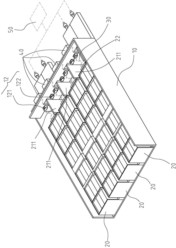
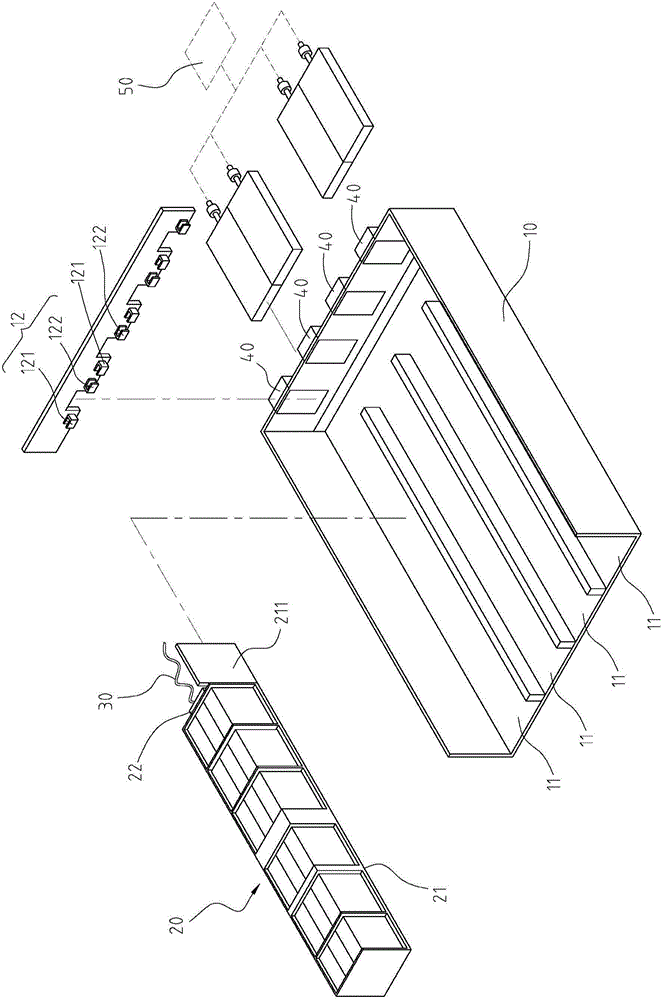
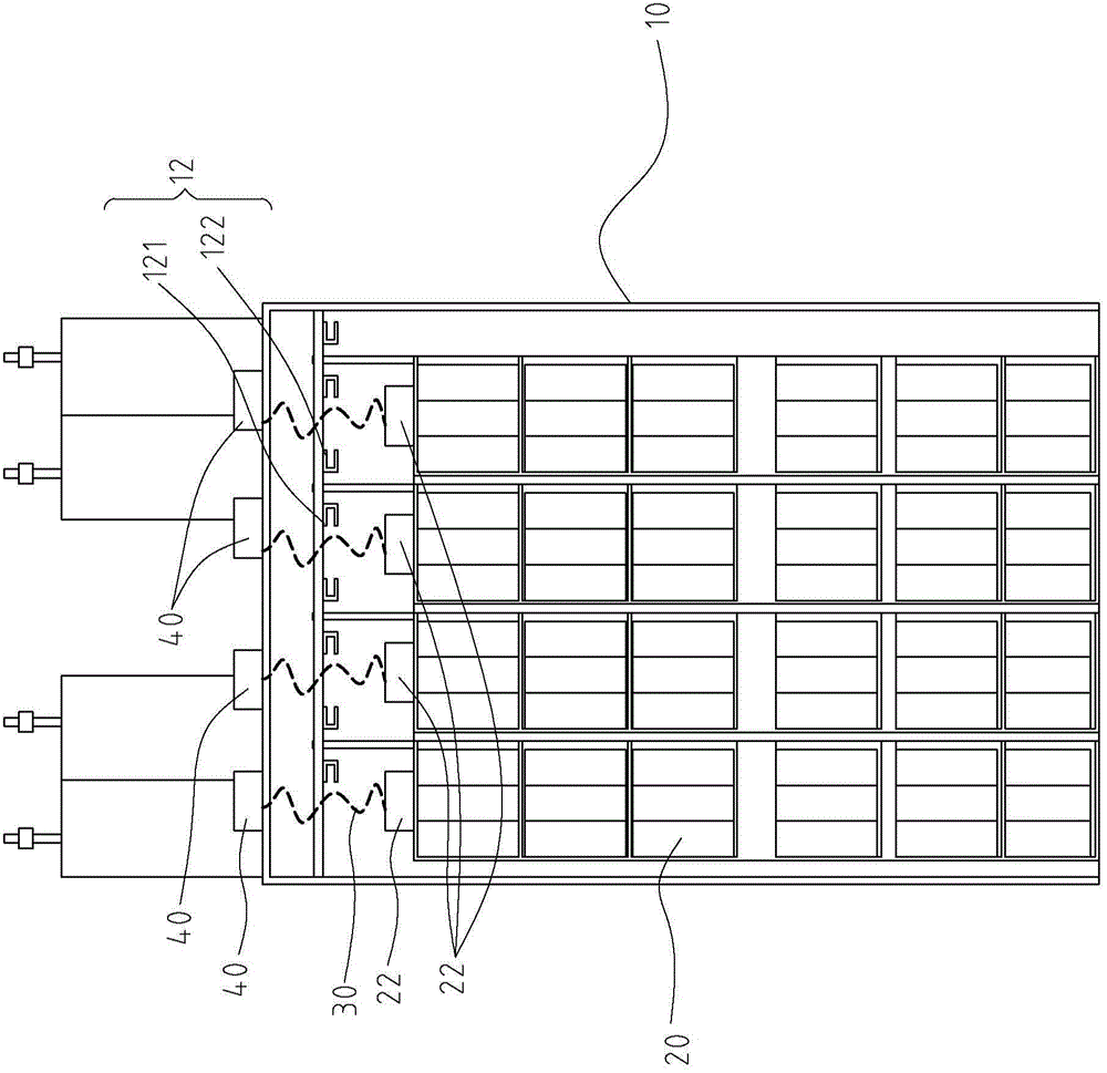
[0038] figure 1 It is a structural diagram of an embodiment of the storage device of the present invention. figure 2 It is a three-dimensional exploded view of an embodiment of the storage device of the present invention. image 3 It is a top view of an embodiment of the storage device of the present invention. see figure 1 , figure 2 , the storage device includes a casing 10 , a storage module 20 , a transmission line 30 and a detection module 40 . The storage module 20 is located in the casing 10 and one side thereof is connected with a transmission line 30 .

[0039] see Figure 1~3 The casing 10 includes at least one accommodating slot 11 and at least one pair of alignment sensors 12 , and the alignment sensors 12 are correspondingly disposed on one side of the accommodating slot 11 . In this embodiment, the alignment sensor 12 is located at the end of the accommodation groove 11, but the present invention is not limited thereto. In other embodiments, the alignment...


PUM


Abstract

The invention relates to a detection system for a storage device and a detection method therefor. The detection system for storage device includes a chassis, a storage module, a transmission wire and a detecting module. The chassis includes a receiving groove and a para-position sensor. The para-position sensor is installed aside of the receiving groove. The storage module corresponds to the receiving groove. The storage module includes a base board and a connecting module installed on the base board. The para-position sensor generates a first structural-error signal when the storage module is not correctly positioned into the receiving groove. The transmission wire is plugged into the connecting module of the storage module and correspondingly coupled with the connecting module. The detecting module is electrically connected to the transmission wire. The detecting module generates a second structural-error signal when the transmission wire is not correctly connected to the connecting module. A structural-error detecting method is also provided. Accordingly, repair personnel can find out and solve the structural errors quickly, and the efficiency of the repair personnel can be improved.

Description

technical field [0001] A detection system and a detection method thereof, in particular a storage device detection system and a detection method thereof. Background technique [0002] With the development of science and technology, the calculation of information is getting bigger and bigger, and the storage space required is also getting bigger and bigger, so the hard disk space required is also getting bigger and bigger. However, the storage space of a single hard disk is limited, and the Therefore, common methods such as disk array (Raid), data center (DataCenter), and cloud hard disk have emerged to store huge amounts of data. [0003] It is common in the market to install multiple main boards in the cabinet, which are respectively inserted into the slots in the cabinet, and each main board is provided with multiple hard drives. The storage space is larger. Generally speaking, in order to quickly repair, when there is a problem with a certain hard disk, the correspondin...

Claims


Application Information

Patent Timeline
Patent Type & Authority Applications(China)
IPC IPC(8): G01R31/02G11C29/56
CPCG06F11/0727G01R31/69G06F11/22
Inventor 蔡家铭谢正光刘育宏彭元晧
Owner WIWYNN CORP
Learn More