Light source module and display device

A technology of light source module and display device, applied in optics, optical elements, instruments, etc., can solve the problems of limited range of incident angle and uneconomical

Inactive Publication Date: 2016-08-03
DELTA ELECTRONICS INC
View PDF6 Cites 2 Cited by
  • Summary
  • Abstract
  • Description
  • Claims
  • Application Information

AI Technical Summary

Problems solved by technology

The range of light incidence angles that can be resolved by the light source module will be limited by its own etendue
Generally, the existing method of increasing etendue is to increase the imaging area of ​​the digital micromirror device. However, as the number of fields of view increases, it is necessary to use a digital micromirror device with special specifications to achieve the required imaging area. less economical

Method used


Image

  • Light source module and display device
  • Light source module and display device
  • Light source module and display device

Examples


Embodiment Construction

[0090] A light source module and a projection device according to preferred embodiments of the present invention will be described below with reference to related drawings, wherein the same elements will be described with the same reference symbols.

[0091] Meanwhile, in the following embodiments and drawings, elements not directly related to the present invention have been omitted and not shown; and the dimensional relationship among the elements in the drawings is only for easy understanding, and is not intended to limit the actual ratio.

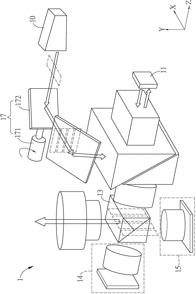
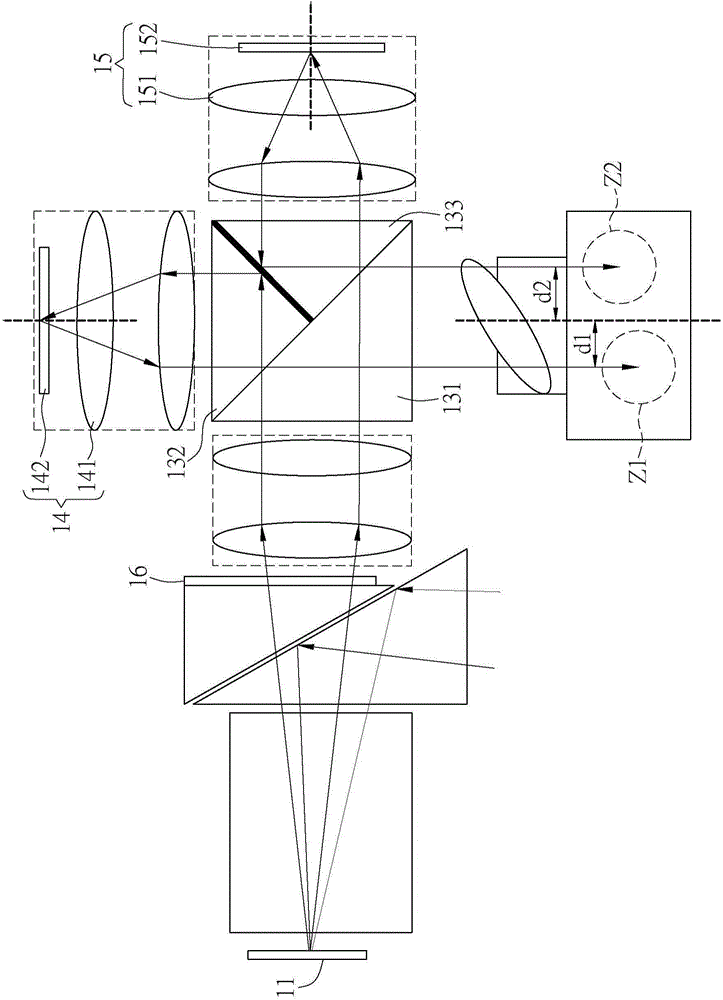
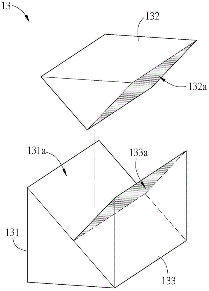
[0092] Please refer to Figure 1 to Figure 3 , figure 1 It is a schematic diagram of the light source module of the present invention. figure 2 for figure 1 Partial view of the light source module. image 3 for figure 1 Exploded schematic diagram of the light splitting unit of the light source module.

[0093] The present invention provides a light source module 1 used in a display device. The display device exemplified herein may...


PUM


Abstract

The invention provides a light source module and a display device. The light source module has a main optical axis, and comprises a light source, an imaging unit, a light splitting unit, a first relay unit, and a second relay unit. The light splitting unit has a transmission surface, a first reflection surface, and a second reflection surface, and the first reflection surface and the second reflection surface are arranged symmetrically. The light source provides light. The light sequentially passes through the imaging unit and the light splitting unit, part of the light forms a first light beam, and part of the light forms a second light beam. There is a first offset between a first optical axis of the first light beam and the main optical axis, there is a second offset between a second optical axis of the second light beam and the main optical axis, the first offset is the same with the second offset, and the offset directions of the first offset and the second offset relative to the main optical axis are opposite. The analyzable field of vision is increased.

Description

technical field [0001] The invention relates to a light source module, in particular to a light source module used for a display device and a display device using the light source module. Background technique [0002] In recent years, with the vigorous development of stereoscopic display technology, various commercial products have emerged, such as stereoscopic movies, stereoscopic TVs, etc., that apply this technology. Stereoscopic display technology is to transmit the left-eye image and right-eye image of different viewing angles to the left eye and right eye of the viewer in a time sequence, imitating the depth of field produced by the human eye due to parallax, and allowing the observer to watch the stereoscopic image . [0003] In addition, it can also be divided into glasses-type, helmet-type and naked-eye stereoscopic display technologies according to whether additional equipment is required. Among them, naked-eye three-dimensional display technology is particularly...

Claims


Application Information

Patent Timeline
IPC IPC(8): G02B27/22G02B27/10
Inventor 黄俊杰
Owner DELTA ELECTRONICS INC
Why Eureka
Try Eureka