Transformer structure with guiding and positioning device and using method of transformer structure

A technology for guiding positioning and transformers, which is applied in the field of transformers and can solve problems such as unfavorable position, collision between personnel and equipment, and difficulty in manually adjusting its position.

Inactive Publication Date: 2016-08-03
范爱苏
View PDF5 Cites 0 Cited by
  • Summary
  • Abstract
  • Description
  • Claims
  • Application Information

AI Technical Summary

Problems solved by technology

Due to the lifting height and considering the depth of the compartment, etc., it usually has a certain height from the final installation position, which is not good for controlling the position of the entire transfo

Method used


Image

  • Transformer structure with guiding and positioning device and using method of transformer structure
  • Transformer structure with guiding and positioning device and using method of transformer structure
  • Transformer structure with guiding and positioning device and using method of transformer structure

Examples


Embodiment Construction

[0011] Combine below Figure 1-4 Embodiments of the present invention will be described.

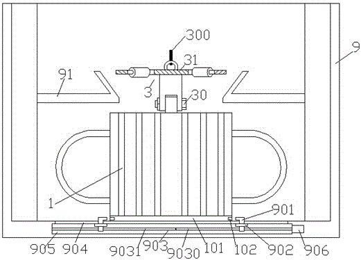
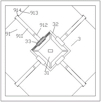
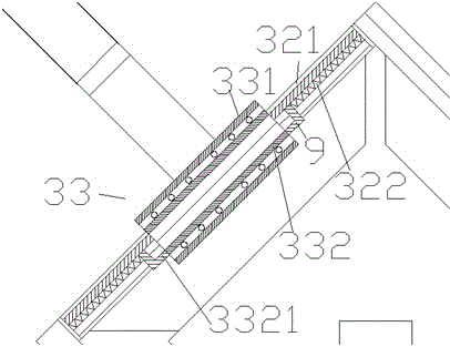
[0012] refer to Figure 1-3 , according to an embodiment of a transformer structure with a guide and positioning device, including a box device 9 with a square section for installing a transformer 1, a slope guide frame assembly 91 installed in the box device 9, and a guide frame assembly for passing through Fasteners 30 are fixed to the positioning joint device 3 of the transformer 1, and the inclined plane guide frame assembly 91 includes corner plates 913 that are respectively hingedly installed at the four corner positions of the compartment device 9 Each of the four slope guide frames includes a rotating arm part 911 hinged with the corner plate 913 through a hinge part 914 and is fixedly connected with the rotating arm part 911 and extends outward from bottom to top. Inclined inclined portion 912; the positioning engagement device 3 includes a square roller support frame 32, a jo...


PUM


Abstract

A transformer structure with a guide and positioning device, comprising a box device (9) with a square cross-section for installing a transformer (1), an inclined guide frame assembly (91) installed in the box device (9), and The positioning joint device (3) used to be fixedly connected with the transformer (1) through fasteners (30), the slope guide frame assembly (91) includes hingedly mounted on the compartment device (9) Four inclined guide frames on the corner plate (913) fixed at the four corner positions, each inclined guide frame includes a rotating arm hinged to the corner plate (913) by a hinge (914) part (911) and the inclined part (912) which is fixedly connected with the rotating arm part (911) and slopes outward from bottom to top; the positioning engagement device (3) includes a square roller support frame (32).

Description

technical field [0001] The invention relates to the field of transformers, in particular to a transformer structure with a guiding and positioning device and a use method thereof. Background technique [0002] Transformers are often installed in transformer compartments for ease of maintenance. During the installation of the transformer, due to its heavy weight, lifting equipment and flexible steel cables are usually used. Due to the lifting height and considering the depth of the compartment, etc., it usually has a certain height from the final installation position, which is unfavorable for controlling the position of the entire transformer equipment during the falling process. Due to the large weight involved, it becomes difficult to manually adjust its position during the fall process, and risks such as collisions of personnel and equipment are prone to occur. Contents of the invention [0003] The object of the present invention is to provide a transformer structure...

Claims


Application Information

Patent Timeline
IPC IPC(8): H01F27/06H01F41/00
CPCH01F27/06H01F41/00
Inventor 范爱苏
Owner 范爱苏
Why Eureka
Try Eureka