Novel micro power generation device

A power generation device and miniature technology, applied in the direction of electromechanical devices, electrical components, etc., can solve the problems of insufficient energy density, small magnet shape, and low power density, etc., and achieve the effect of simple structure, reduced influence, and increased power density

Active Publication Date: 2016-08-03
QINGDAO AUGREENER ELECTRONICS TECH
View PDF5 Cites 2 Cited by
  • Summary
  • Abstract
  • Description
  • Claims
  • Application Information

AI Technical Summary

Problems solved by technology

With the development of miniaturization, the energy density of existing micro power generation modules often cannot meet the requirements, and the process is complicated. At the same time, due to the limitation of the magnetic conductive sheet, the shape of the magnet is smaller, resulting in a lower power density.

Method used


Image

  • Novel micro power generation device
  • Novel micro power generation device
  • Novel micro power generation device

Examples


Embodiment 1

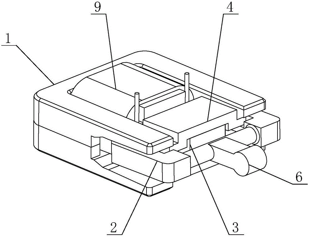
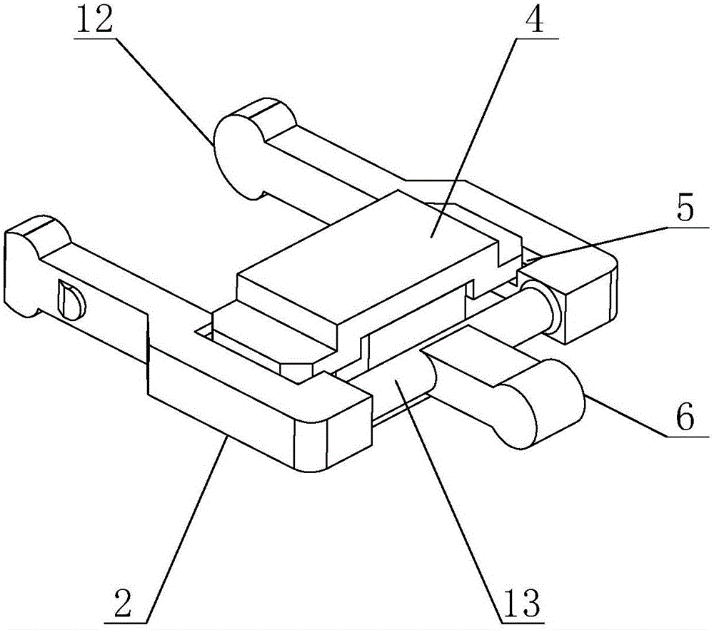
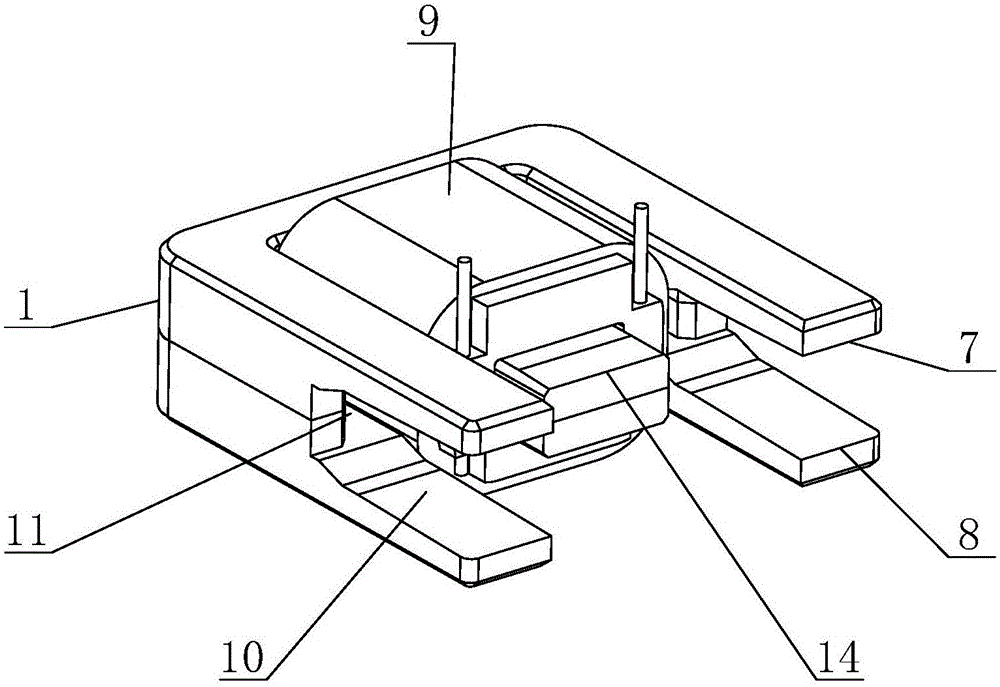
[0033]A novel miniature power generation device comprises moving parts and an iron core 1 matched with the moving parts. The moving parts include a magnet frame 2, a magnet 3 and a magnetically conductive sheet 4. Mounting grooves 5 are arranged on both sides of the magnet frame 2, and a magnetically conductive sheet 4 is installed in the mounting groove 5. The magnetically conductive sheet includes an upper magnetically conductive sheet. sheet 41 and the lower magnetically conductive sheet 42, the magnet 3 is located between the two magnetically conductive sheets 4, the magnet is always close to the magnetically conductive sheet, and the thickness of the magnet is d3. One end of the magnet frame 2 is provided with an operation head 6, and the end of the magnet frame 2 away from the operation head 6 extends into the inside of the iron core 1, and the magnet frame 2 rotates around the iron core 1, and the inner wall of the iron core 1 is provided with Assembling groove 11, desc...

Embodiment 2

[0035] A novel miniature power generation device comprises moving parts and an iron core 1 matched with the moving parts. The moving parts include a magnet frame 2, a magnet 3 and a magnetically conductive sheet 4. Mounting grooves 5 are arranged on both sides of the magnet frame 2, and a magnetically conductive sheet 4 is installed in the mounting groove 5. The magnetically conductive sheet includes an upper magnetically conductive sheet. sheet 41 and the lower magnetically conductive sheet 42, the magnet 3 is located between the two magnetically conductive sheets 4, the magnet is always close to the magnetically conductive sheet, and the thickness of the magnet is d3. One end of the magnet frame 2 is provided with an operation head 6, and the end of the magnet frame 2 away from the operation head 6 extends into the inside of the iron core 1, and the magnet frame 2 rotates around the iron core 1, and the inner wall of the iron core 1 is provided with Assembling groove 11, des...


PUM


Abstract

The invention discloses a novel micro power generation device, and relates to the technical field of power generation devices. The novel micro power generation device comprises a moving part. The upper and lower sides of a magnet frame are each provided with a mounting slot. A magnetic conductive plate is mounted in each mounting slot. A magnet is disposed between the two magnetic conductive plates, and the thickness of the magnet is d3. One end of the magnet frame is provided with an operation head. One end of the magnet frame extends into a core, and the magnet frame rotates about the core. A limiting device is arranged on the core, and the limiting device forms an upper movement stop point and a lower movement stop point. The core is wound with a coil. The distance between the inner sides of two magnetic conductive plates in areas matching branch magnetic circuits is d4 which is smaller than d3. The novel micro power generation device has the beneficial effects as follows: the device has a simple structure; the size of modules is reduced; and through the magnetic conductive plates, a largest possible magnet can be used in the limited size while a spacing is kept, so that the power density is improved, and the production process is simplified greatly.

Description

technical field [0001] The invention relates to the technical field of power generation devices, in particular to a novel micro power generation device. Background technique [0002] In recent years, with the development of passive wireless devices, more and more new usage requirements have been put forward, and the existing generator models do not meet some new usage requirements, so it is imminent to develop a new type of generator. With the development of miniaturization, the energy density of existing micro power generation modules often cannot meet the requirements, and the process is complicated. At the same time, due to the limitation of the magnetic conductive sheet, the shape of the magnet is small, resulting in a small power density. Contents of the invention [0003] In order to solve the deficiencies in the prior art, the present invention provides a new type of micro power generation device, which has a simple structure, reduces the module volume, and through ...

Claims


Application Information

Patent Timeline
Patent Type & Authority Applications(China)
IPC IPC(8): H02K35/02
CPCH02K35/02
Inventor 安邦
Owner QINGDAO AUGREENER ELECTRONICS TECH
Why Eureka
Try Eureka