Radio frequency signal transceiving device and electronic apparatus
A technology of radio frequency signal, transceiver device, applied in the field of electronics, can solve the problems of tight layout space and insufficient number of antenna switch ports, and achieve the effect of reducing radio frequency devices, reducing the demand for antenna switch ports, and saving layout space
- Summary
- Abstract
- Description
- Claims
- Application Information
AI Technical Summary
Problems solved by technology
Method used
Image
Examples
no. 1 example
[0020] Such as figure 2 As shown, the first embodiment of the present invention provides a radio frequency signal transceiving device, the radio frequency signal transceiving device includes: a transceiver; an amplifying unit connected to the transceiver; a first radio frequency signal for transmitting a first frequency band A path, and the first path is connected to the amplifying unit; a second path for transmitting a second radio frequency signal of the second frequency band, and the second path is connected to the amplifying unit; and a third radio frequency signal for receiving the first frequency band and The third path of the fourth radio frequency signal of the second frequency band, and the third path is connected with the transceiver.
[0021] In the first embodiment of the present invention, the above-mentioned first frequency band and the second frequency band may be respectively the wireless communication frequency band B39 (the frequency band is 1880-1920 MHz) a...
no. 2 example
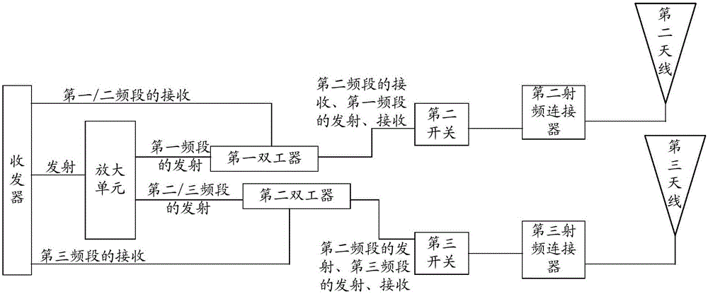
[0032] Such as image 3 As shown, the second embodiment of the present invention provides a radio frequency signal transceiving device, the radio frequency signal transceiving device includes: a transceiver; an amplifying unit connected to the transceiver; a first radio frequency signal for transmitting a first frequency band A path, and the first path is connected to the amplifying unit; a second path for transmitting the second radio frequency signal of the second frequency band, and the second path is connected to the amplifying unit; used for receiving the third radio frequency signal of the first frequency band and the second radio frequency signal The third path of the fourth radio frequency signal of the second frequency band, and the third path is connected with the transceiver, and the fourth path for receiving the fifth radio frequency signal of the third frequency band, and the second path is also used for transmitting the third frequency band. The sixth radio frequ...
no. 3 example
[0045] Such as Figure 4 As shown, the third embodiment of the present invention provides a radio frequency signal transceiving device, the radio frequency signal transceiving device includes: a transceiver; an amplifying unit connected to the transceiver; a first radio frequency signal for transmitting a first frequency band A path, and the first path is connected to the amplifying unit; a second path for transmitting the second radio frequency signal of the second frequency band, and the second path is connected to the amplifying unit; used for receiving the third radio frequency signal of the first frequency band and the second radio frequency signal The third path of the fourth radio frequency signal of the second frequency band, and the third path is connected with the transceiver, and the fourth path for receiving the fifth radio frequency signal of the third frequency band, and the second path is also used for transmitting the third frequency band. The sixth radio frequ...
PUM
 Abstract
Description
Claims
Application Information
 - R&D
- Intellectual Property
- Life Sciences
- Materials
- Tech Scout
- Unparalleled Data Quality
- Higher Quality Content
- 60% Fewer Hallucinations
Browse by: Latest US Patents, China's latest patents, Technical Efficacy Thesaurus, Application Domain, Technology Topic, Popular Technical Reports.
© 2025 PatSnap. All rights reserved.Legal|Privacy policy|Modern Slavery Act Transparency Statement|Sitemap|About US| Contact US: help@patsnap.com


