
Variable stator vane mechanism

A static vane, variable technology, applied in mechanical equipment, non-variable pumps, engine manufacturing, etc., can solve problems such as engine starting block and inability to start

Inactive Publication Date: 2016-08-03
KAWASAKI JUKOGYO KK
View PDF8 Cites 5 Cited by
  • Summary
  • Abstract
  • Description
  • Claims
  • Application Information

AI Technical Summary

Problems solved by technology

In this unstable state, if the gas turbine engine is operated for a long time, the engine will be blocked and the start cannot be completed.

Method used


Image

  • Variable stator vane mechanism
  • Variable stator vane mechanism
  • Variable stator vane mechanism

Examples


Embodiment Construction

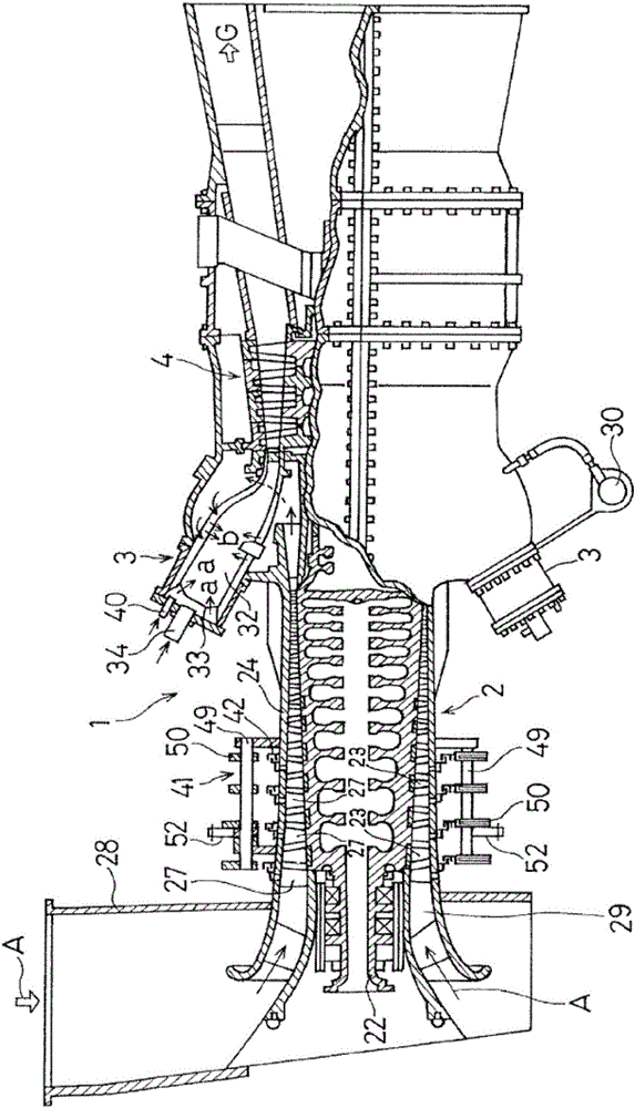
[0034] Next, preferred embodiments of the present invention will be described with reference to the drawings. figure 1 A partially cutaway schematic side view showing a gas turbine engine employing a variable vane mechanism is shown. exist figure 1 Among them, the gas turbine engine 1 has a structure in which air is compressed by an axial flow compressor 2 and introduced into a combustor 3, and a gaseous fuel such as city gas is injected into the combustor 3 for combustion. The high temperature and high pressure combustion gas can drive the turbine 4 . The turbine 4 drives an unillustrated generator while driving the axial compressor 2 .

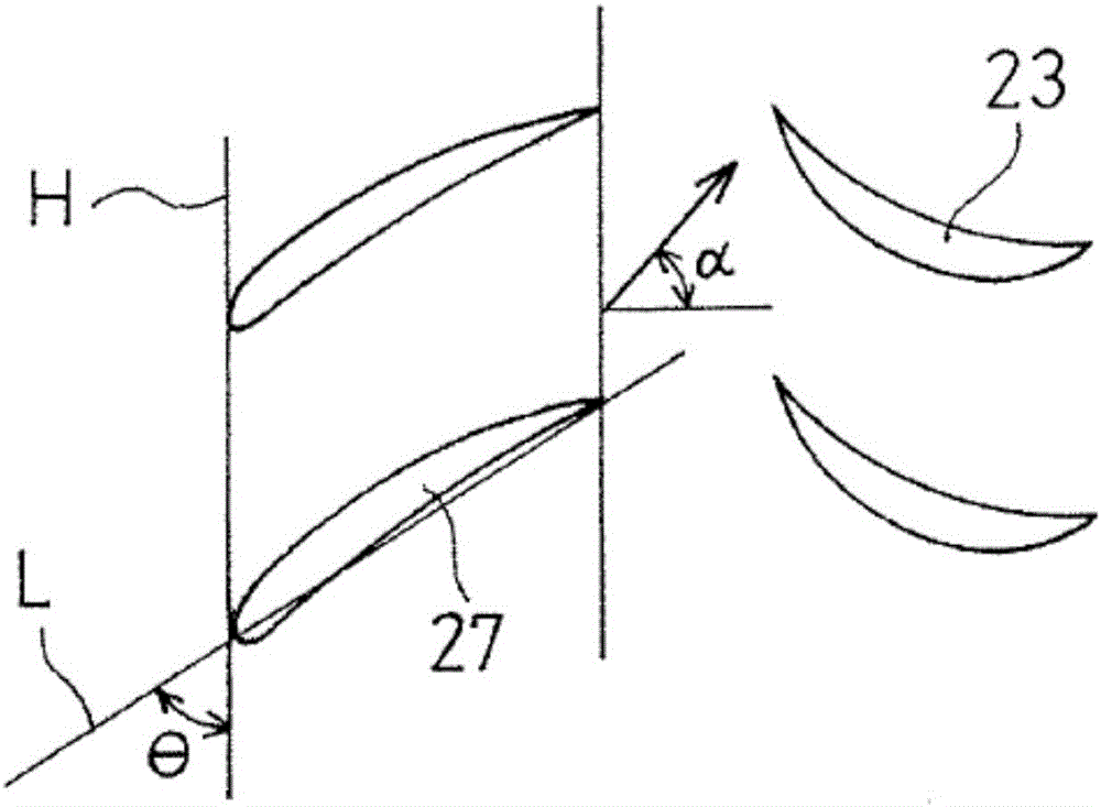
[0035] The axial flow compressor 2 compresses the air A sucked in from the suction cylinder 28 by a combination of a plurality of moving blades 23 arranged on the outer peripheral surface of the rotating shaft 22 and stationary blades 27 arranged in multiple stages on the inner peripheral surface of the casing 24, and the The compressed a...


PUM


Abstract

Provided is a variable stator vane mechanism for an axial compressor that has excellent durability and a simple structure at a low cost. This variable stator vane mechanism is for adjusting the mounting angle of a stator vane (27) of an axial compressor (2), and is equipped with an arm (44) that is connected to the stator vane (27), a rotary ring (42) that is connected to one end (44b) of the arm (44) and positioned on the periphery of a casing (24) of the axial compressor (2), a driver (53) that rotates the rotary ring (42), thereby causing the stator vane (27) to be rotated via the arm (44), and a friction pad (67) that is mounted on the casing (24). The rotary ring (42) is in frictional contact with the friction pad (67).

Description

[0001] related application [0002] This application claims the priority of Japanese Patent Application No. 2013-262426 for which it applied on December 19, 2013, The content is taken in as a part by reference as a part of this application. technical field [0003] The present invention relates to a variable vane mechanism for adjusting the installation angle of the vane of an axial flow compressor used in a gas turbine engine, a turbo refrigerator, and the like. Background technique [0004] In a gas turbine engine, an axial compressor is used to compress gas. In a gas turbine engine, the intake air is compressed to high pressure by an axial compressor and directed to the combustor. The high-temperature and high-pressure gas burned in the combustor is recovered as rotational energy in the turbine, and then discharged. The compressor of a gas turbine can become unstable during engine start-up known as spinning stall. In this unstable state, if the gas turbine engine is op...

Claims


Application Information

Patent Timeline
Patent Type & Authority Applications(China)
IPC IPC(8): F04D29/56
CPCF01D17/162F04D29/563F05D2250/40
Inventor 池口拓也中山健太郎
Owner KAWASAKI JUKOGYO KK
Learn More