In-situ electric heating desorption restoration technology and device for contaminated site

An electric heating and field technology, applied in the field of soil remediation, can solve the problems of easily damaged heating pipes, high energy consumption, and inability to effectively and stably control the heating temperature of polluted areas, so as to ensure the restoration effect, high degree of automation, and safety of energy saving and consumption reduction The effect of stability

Active Publication Date: 2016-08-10
SHANGHAI GREENMENT ENVIRONMENTAL TECH CO L
View PDF4 Cites 25 Cited by
  • Summary
  • Abstract
  • Description
  • Claims
  • Application Information

AI Technical Summary

Benefits of technology

This patented technology allows for efficient and cost-effective cleanup of contaminated areas while minimizing environmental impact. It involves converting electrical (E) energy into heat instead of burning it or storing it separately. By controlling the amount of Ethernet cable needed, the method enables more precise placement of heaters within specific locations. Additionally, there're also an improved safety feature where sensors monitor the surrounding temperatures and provide signals when necessary. Overall, these improvements improve the performance and functionality of existing methods such as flameless incinerators and chemical solvent treatments.

Problems solved by technology

This patented describes different techniques that are commonly utilized by industry to recover contaminated areas such as those found near highly challengingly organically distributed sources like heavy metals (Cd) and organochlorine compound(VCC). These technologies use physical processes involving burning fossils fuel with oxygen containing gases at very high temperatures, causing harmful environmental impacts due to their negative effect on humans' wellbeings. However, current treatment options require long periods of exposure while maintaining effective removal rates of target materials.

Method used


Image

  • In-situ electric heating desorption restoration technology and device for contaminated site
  • In-situ electric heating desorption restoration technology and device for contaminated site
  • In-situ electric heating desorption restoration technology and device for contaminated site

Examples


Embodiment Construction

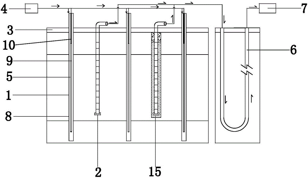
[0028] Below in conjunction with accompanying drawing, the present invention will be further described with specific embodiment: see Figure 1-6 ,

[0029] The in-situ electric heating desorption repair technology for polluted sites includes the following steps:

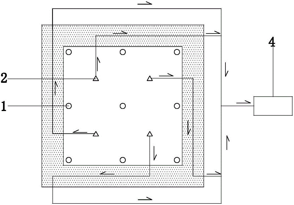
[0030] a. Insert several heating wells 1 and extraction wells 2 into the polluted site, the insertion depth is 1-4 meters;

[0031] b. Lay a thermal insulation layer 3 on the surface of the polluted site, and the thermal insulation layer is made of lightweight concrete;

[0032] c. Treat the groundwater in the polluted site as precipitation, and lower the groundwater to a position 5 meters below the ground;

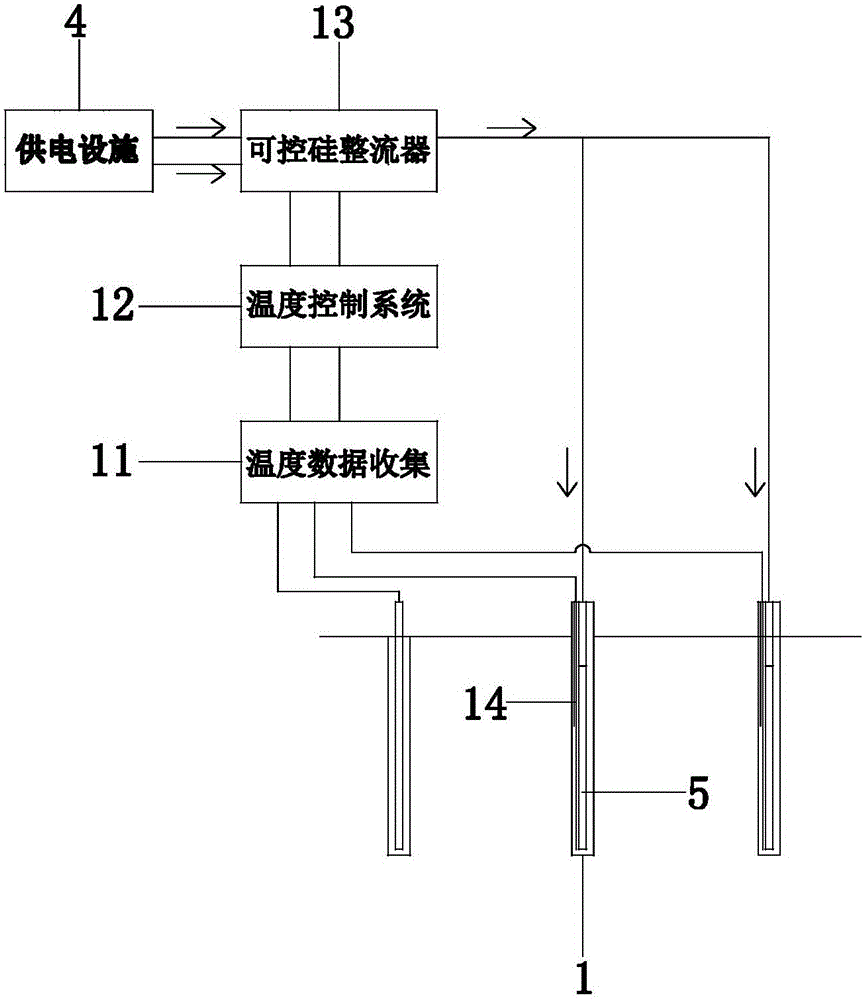
[0033] d. The power supply facility 4 is electrically connected to several heating wells 1 and extraction wells 2, the heating pipe 5 in the heating well 1 is used to heat the polluted site, and the vacuum pump in the extraction well is used to pump out the gaseous pollutants and pollution generated in the pol...


PUM


Abstract

The invention provides an in-situ electric heating desorption restoration technology and device for a contaminated site, belongs to the technical field of soil restoration, and solves the problems that soil and underground water are polluted due to industrial pollution and agricultural chemistry, and the like. The in-situ electric heating desorption restoration technology for the contaminated site comprises the steps of a, inserting a plurality of heating wells and extraction wells into the contaminated site; b, paving a thermal insulating layer on the surface of the contaminated site; c, carrying out precipitation treatment on the underground water of the contaminated site; d, heating the contaminated site through heating pipes in the heating wells, and extracting gaseous pollutants generated by the heated contaminated site and polluted underground water through vacuum pumps in the extraction wells, so as to restore the contaminated site; and e, feeding the gaseous pollutants and the polluted underground water extracted in the step d into a border thermal cycle pipe buried in a stratum at the border for secondary heat exchange, and then feeding the gaseous pollutants and the polluted underground water subjected to secondary heat exchange into a ground extraction treatment device for treatment. The in-situ electric heating desorption restoration technology has the advantages that full automatic temperature control is achieved, waste heat is fully reused, the layout is flexible, a higher scientific and technological level is reached, and the like.

Description


Claims


Application Information

Patent Timeline
Owner SHANGHAI GREENMENT ENVIRONMENTAL TECH CO L
Why Eureka
Try Eureka