Three-way clamping device

A clamping device and cylinder technology, applied in the field of machining, can solve the problems of large cylinder diameter, low pressure, increased cost, etc., and achieve the effects of improving output pressure, compact structure and reducing manufacturing cost

Inactive Publication Date: 2016-08-10
SICHUAN HANGDA ELECTROMECHANICAL TECH DEV SERVICE CENT
View PDF0 Cites 16 Cited by
  • Summary
  • Abstract
  • Description
  • Claims
  • Application Information

AI Technical Summary

Problems solved by technology

[0002] In enterprise production, workpieces with relatively large rough machining area and machining allowance often require large cutting force. In order to balance the large cutting force, the fixture design often needs to clamp the workpiece in three directions. The three directions generate a large clamping force and keep it stable. Pneumatic transmission is a convenient, reliable, efficient and clean way of applying force. However, since the pressure of the pneumatic transmission system is not high, if it is designed according to the conventional method, in three directions Selecting three cylinders or two cylinders for pressurization can solve the problem of three-way pressure, but it often causes the problem of excessive cylinder diameter, and using multiple cylinders at the same time will increase the manufacturing cost

Method used


Image

  • Three-way clamping device

Examples


Embodiment Construction

[0009] The present invention will be further described below in conjunction with the accompanying drawings.

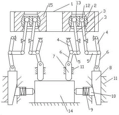
[0010] refer to figure 1 , is a three-way clamping device, including a cylinder 1, the cylinder 1 is a double-piston cylinder, the cylinder piston 15 is provided with a floating block 2, and the floating block 2 is provided with two sliding holes 13, so The two sliding holes 13 are respectively connected with lever mechanisms, wherein one lever mechanism is connected with a compression rod 7, and the other lever mechanism is connected with a wedge block 8, and the inclined surface of the wedge block 8 is connected with a compression guide rod 10. , the compression rod 7 and the compression guide rod 10 move along the guide sleeve 11 respectively, and the compression guide rod 10 is provided with a return spring 9 .

[0011] Described lever mechanism is made up of movable ball head 6, fixed rod 3, fixed hinge rod 4, pull bar 5, movable hinge rod 6, and described movabl...


PUM


Abstract

Provided is a three-way clamping device, comprising a cylinder. The cylinder is a double-piston cylinder. A cylinder piston is internally provided with a floating block. The floating block is internally provided with two sliding holes. The two sliding holes are each connected with a lever mechanism, wherein one lever mechanism is connected with a compressing rod, and the other lever mechanism is connected with an inclined wedge. The slope of the inclined wedge is connected with a compressing guide rod. The compressing rod and the compressing guide rod respectively move along a guide sleeve. The compressing guide rod is provided with a reset spring. The device uses a single cylinder and realizes three-way clamping on a workpiece. The device is compact in structure and reliable in clamping, and manufacturing cost is reduced, and the device is simple and practical.

Description

technical field [0001] The invention relates to the technical field of mechanical processing, in particular to a clamping device capable of clamping workpieces in three directions at the same time. Background technique [0002] In enterprise production, workpieces with relatively large rough machining area and machining allowance often require large cutting force. In order to balance the large cutting force, the fixture design often needs to clamp the workpiece in three directions. The three directions generate a large clamping force and keep it stable. Pneumatic transmission is a convenient, reliable, efficient and clean way of applying force. However, because the pressure of the pneumatic transmission system is not high, if it is designed according to the conventional method, in three directions Selecting three cylinders or two cylinders for pressurization can solve the problem of applying pressure in three directions, but it often causes the problem that the diameter of t...

Claims


Application Information

Patent Timeline
Patent Type & Authority Applications(China)
IPC IPC(8): B23Q3/08
Inventor 林敏
Owner SICHUAN HANGDA ELECTROMECHANICAL TECH DEV SERVICE CENT
Why Eureka
Try Eureka