A centralized multi-condition thermal management system for new energy vehicles

A technology of new energy vehicles and thermal management systems, applied in the field of centralized multi-working-condition thermal management systems, can solve problems such as system complexity and cost increase, thermal management system function limitations, and inability to provide thermal management, etc., to reduce complexity degree, cost saving, and beneficial to the layout of the whole vehicle

Active Publication Date: 2018-11-09
CH AUTO TECH CORP CO LTD
View PDF6 Cites 0 Cited by
  • Summary
  • Abstract
  • Description
  • Claims
  • Application Information

AI Technical Summary

Problems solved by technology

The disadvantage of this method is: when cooling the passenger compartment, the system can only provide cooling thermal management for the power battery pack; when heating the passenger compartment, the system can only provide heating thermal management for the power battery pack. thermal management
In this way, the function of the thermal management system is limited, and it cannot provide corresponding thermal management in time according to the actual needs of the power battery pack. Therefore, some centralized thermal management systems add a separate heating device for the power battery pack to solve this problem. One problem, but this increases the complexity and cost of the system

Method used


Image

  • A centralized multi-condition thermal management system for new energy vehicles

Examples


Embodiment Construction

[0016] In order to further explain the technical means and effects adopted by the present invention to achieve the intended purpose of the invention, the following describes the centralized multi-working-condition thermal management system of a new energy vehicle proposed according to the present invention in conjunction with the accompanying drawings and preferred embodiments. Specific implementation, steps, structures, features and effects thereof are described in detail.

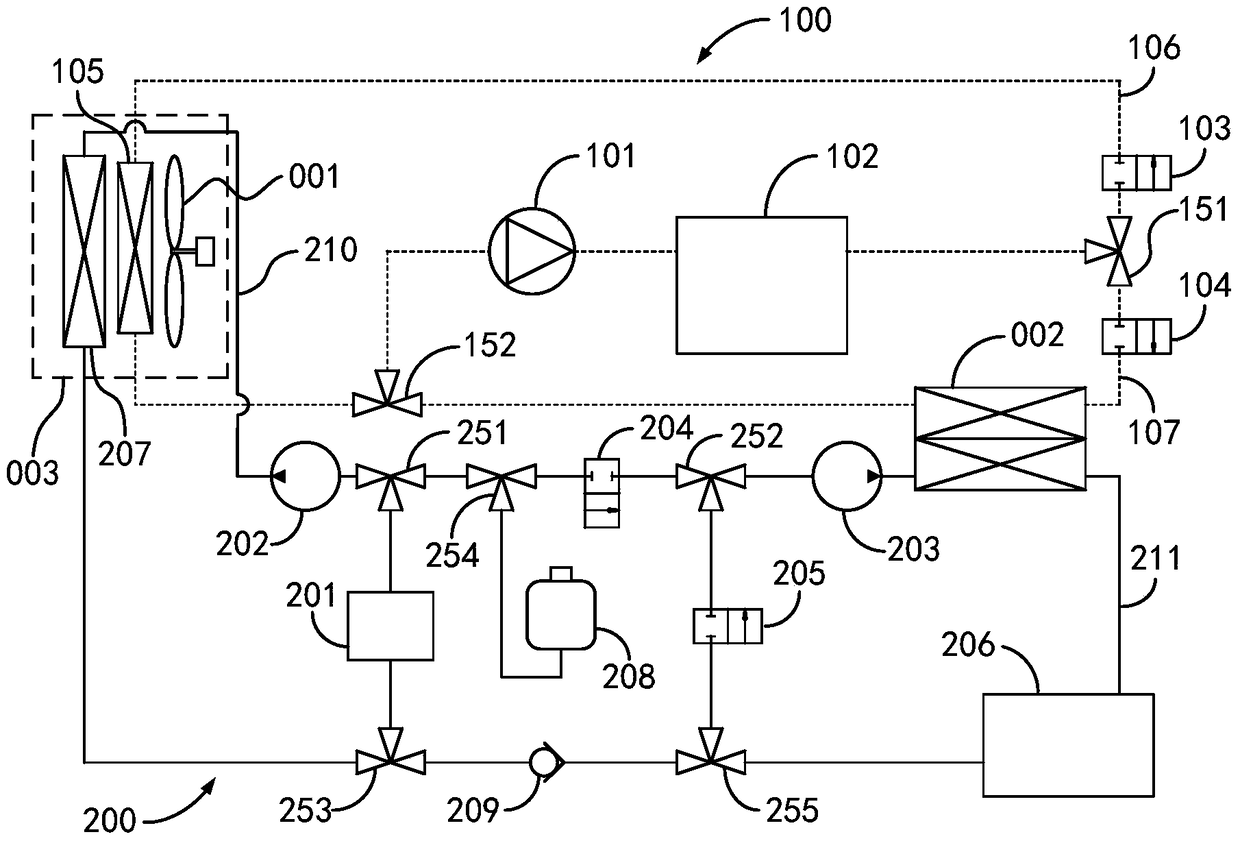
[0017] see figure 1 As shown, it is a schematic diagram of a preferred embodiment of a centralized multi-working-condition thermal management system for a new energy vehicle according to the present invention.

[0018] A centralized multi-working-condition thermal management system for a new energy vehicle of the present invention is used for the thermal management of the passenger compartment and power battery pack of the new energy vehicle, and is mainly composed of a refrigerant circuit 100 and a coola...


PUM


Abstract

The invention relates to a centralized multi-operating-condition thermal management system of a new energy vehicle. The centralized multi-operating-condition thermal management system comprises a refrigerant circuit and a cooling liquid circuit; the refrigerant circuit comprises a compressor, a condenser connected with the compressor, a passenger compartment refrigerant branch circuit and a power battery pack refrigerant branch circuit, wherein the passenger compartment refrigerant branch circuit and the power battery pack branch circuit are connected to the two ends of the compressor and the condenser in parallel; the passenger compartment refrigerant branch circuit comprises an electromagnetic valve and an evaporator for heating a passenger compartment; the power battery pack branch circuit comprises an electromagnetic valve and a heat exchanger for lowering the temperature of cooling liquid; the cooling liquid circuit comprises a PTC heater, a passenger compartment cooling liquid branch circuit and a power battery pack cooling liquid branch circuit, wherein the passenger compartment cooling liquid branch circuit and the power battery pack cooling liquid branch circuit are connected to the two ends of the PTC heater in parallel; the passenger compartment cooling liquid branch circuit comprises a pump and a heater for heating the passenger compartment; the power battery pack cooling liquid branch circuit comprises an electromagnetic valve, a pump, a heat exchanger, a power battery pack, a reflux valve and a one-way valve. According to the centralized multi-operating-condition thermal management system of the new energy vehicle, one set of refrigerating / heating elements can be used for conducting independent thermal management on the passenger compartment and the power battery pack of the new energy vehicle.

Description

technical field [0001] The present invention relates to a thermal management system, in particular to a centralized thermal management of a new energy vehicle for a passenger compartment and a power battery pack by using the same set of cooling / heating elements, and the thermal management of the passenger compartment and the power battery pack can be Centralized multi-condition thermal management system for new energy vehicles that operate independently. Background technique [0002] Early new energy vehicles used an independent thermal management system, which divided the thermal management system of the passenger compartment and the thermal management system of the power battery pack into two independent parts. Although this thermal management system can meet the thermal management requirements of the passenger compartment and the power battery pack separately, since both systems need to meet their own thermal management requirements, the system is redundant and the perfor...

Claims


Application Information

Patent Timeline
Patent Type & Authority Patents(China)
IPC IPC(8): B60H1/00H01M10/613H01M10/615H01M10/625H01M10/6567H01M10/6571
CPCY02E60/10
Inventor 张宇
Owner CH AUTO TECH CORP CO LTD
Why Eureka
Try Eureka