Centralized cutting fluid supply device for metal machining machine tools

A metal processing and supply device technology, applied to metal processing machinery parts, metal processing equipment, mixers, etc., can solve the problems of low practicability, inability to guarantee the normal development of metal processing operations, and failure to achieve centralized supply, etc., to achieve practicality high effect

Inactive Publication Date: 2021-12-03
江西逸辰企业咨询有限公司
View PDF0 Cites 4 Cited by
  • Summary
  • Abstract
  • Description
  • Claims
  • Application Information

AI Technical Summary

Problems solved by technology

[0003] Metal processing machine tools need to use cutting fluid for cooling and lubrication during operation. However, there are still some deficiencies in the supply devices used for cutting fluid in metal processing machine tools. For example, most of the supply devices used for cutting fluid in existing metal processing machine tools are supplied separately , centralized supply has not been realized, resulting in the need to manually add cutting fluid to multiple groups of metal processing machine tools in sequence, which is less practical, and there is no stirring mechanism in the liquid storage tank used by the existing cutting fluid, resulting in storage The cutting fluid in the liquid tank will be unevenly mixed after a long period of precipitation, which cannot guarantee the normal development of metal processing operations on subsequent metal processing machine tools. Therefore, we propose a centralized supply device for cutting fluid for metal processing machine tools. solve the above problems

Method used


Image

  • Centralized cutting fluid supply device for metal machining machine tools
  • Centralized cutting fluid supply device for metal machining machine tools
  • Centralized cutting fluid supply device for metal machining machine tools

Examples


Embodiment Construction

[0025] The following will clearly and completely describe the technical solutions in the embodiments of the present invention with reference to the accompanying drawings in the embodiments of the present invention. Obviously, the described embodiments are only some, not all, embodiments of the present invention. Based on the embodiments of the present invention, all other embodiments obtained by persons of ordinary skill in the art without making creative efforts belong to the protection scope of the present invention.

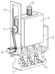
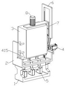
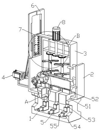
[0026] see Figure 1-8 , the present invention provides a technical solution: a centralized cutting fluid supply device for metal processing machine tools, including a first bracket 1, the top of the first bracket 1 is fixedly connected with a second bracket 2, and the inner upper end of the second bracket 2 is provided with a storage tank. The liquid tank 3 is provided with a corresponding infusion tube, so as to facilitate the introduction of cutting fluid i...


PUM


Abstract

The invention discloses a centralized cutting fluid supply device for metal machining machine tools. The centralized cutting fluid supply device comprises a first support, a second support is fixedly connected to the top end of the first support, a fluid storage tank is arranged at the upper end of the inner side of the second support, a fluid separation mechanism used in cooperation with the fluid storage tank is arranged on the second support, the first support and the second support are provided with liquid supply mechanisms used in cooperation with the liquid separation mechanism, the upper end of one side of the second support is fixedly provided with a U-shaped frame, the U-shaped frame and the second support are provided with reciprocating mechanisms used in cooperation with the liquid separation mechanism, and the upper ends of one sides of the reciprocating mechanisms are provided with stirring mechanisms used in cooperation with the liquid storage tank. A user can open three supply pumps, so that cutting fluid is guided to the three metal machining tools through a transverse pipe, equal-interval equal-amount centralized supply of the cutting fluid is achieved, the phenomenon that the cutting fluid is manually added to the three metal machining tools for multiple times is avoided, and practicability is higher.

Description

technical field [0001] The invention relates to the technical field of metal processing machine tools, in particular to a centralized cutting fluid supply device for metal processing machine tools. Background technique [0002] A machine tool refers to a machine that manufactures a machine, also known as a machine tool or a tool machine, and is customarily referred to as a machine tool. Generally divided into metal cutting machine tools, forging machine tools and woodworking machine tools. There are many ways to process mechanical parts in modern machinery manufacturing: in addition to cutting, there are also casting, forging, welding, stamping, extrusion, etc. The final machining is done by cutting on the machine tool. Machine tools play an important role in the modernization of the national economy. [0003] Metal processing machine tools need to use cutting fluid for cooling and lubrication during operation. However, there are still some deficiencies in the supply devi...

Claims


Application Information

Patent Timeline
Patent Type & Authority Applications(China)
IPC IPC(8): B23Q11/10B01F11/00
CPCB23Q11/10
Inventor 杨柳锋杨伦
Owner 江西逸辰企业咨询有限公司
Why Eureka
Try Eureka