

Variable-rigidity foot system of biped robot
A biped robot and rigidity technology, applied in the field of robotics, can solve problems such as easy instability and falls, high performance requirements for control algorithms and control systems, and achieve the effect of ensuring walking and improving stability
- Summary
- Abstract
- Description
- Claims
- Application Information
AI Technical Summary
Problems solved by technology
Method used
Image

Examples
specific Embodiment approach 1
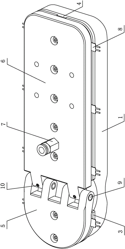
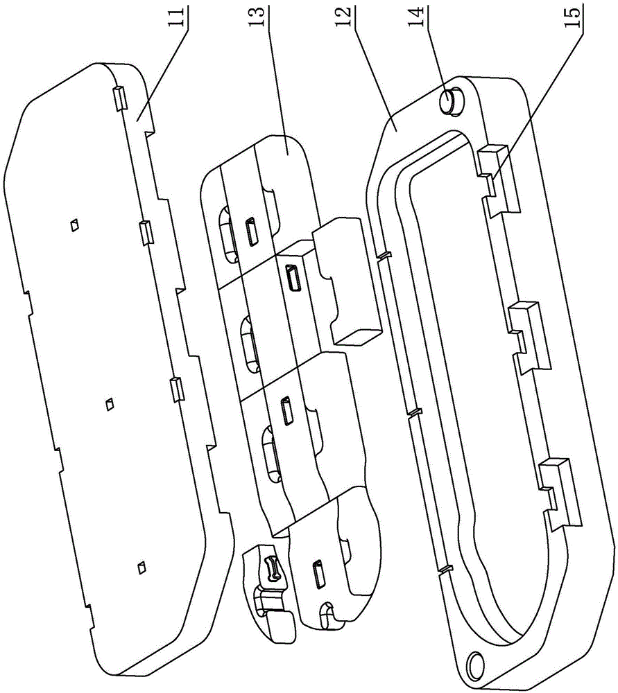
[0009] Specific implementation mode one: combine figure 1 Illustrate, a kind of variable rigidity biped robot foot system of the present embodiment, it comprises sole 1 and instep; Instep support layer 6, pneumatic quick change joint 7 and a plurality of pressure sensors 8; front instep middle layer 3 and rear instep middle layer 4 form the instep middle layer; front instep support layer 5 and rear instep support layer 6 form the foot back support layer;
[0010] The sole 1 is made of a silicone air cushion, the silicone air cushion has multiple air chambers through it, and the upper end surface of the sole 1 is equipped with a front dorsum middle layer 3 and a back dorsum middle layer 4; The front dorsum middle layer 3 and the back dorsum middle layer 4 are respectively arranged on the upper end surface of the silicone air cushion, the upper end surface of the front dorsum middle layer 3 is provided with the front dorsal support layer 5, and the upper end surface of the back...
specific Embodiment approach 2
[0013] Specific implementation mode two: combination figure 1 Explain, the front instep middle layer 3 and the rear instep middle layer 4 of this embodiment are all polyoxymethylene resin middle layers. Such arrangement has high strength, high rigidity, good elasticity, good wear reduction and wear resistance. Protect the air cushion from wear and tear, ensure the easy replacement of the silicone air cushion, and also protect the pressure sensor. Others are the same as in the first embodiment.
specific Embodiment approach 3
[0014] Specific implementation mode three: combination figure 1 Explain that the front instep support layer 5 and the back instep support layer 6 of this embodiment are both polyoxymethylene resin support layers. Such arrangement has high strength, high rigidity, good elasticity, good wear reduction and wear resistance, and protects the pressure sensor. Others are the same as in the first or second embodiment.
PUM
 Abstract
Description
Claims
Application Information