Difference sum circuit in lateral logging tool

A lateral logging and circuit technology, applied in the field of differential sum circuits, can solve problems such as signal acquisition result errors, and achieve the effects of improving measurement accuracy and reducing errors

Active Publication Date: 2021-02-26
CNPC GREATWALL DRILLING ENG +1
View PDF8 Cites 0 Cited by
  • Summary
  • Abstract
  • Description
  • Claims
  • Application Information

AI Technical Summary

Problems solved by technology

Due to the reason of the sum and difference circuit itself, there may be relatively large errors in the signal acquisition results, so a processing circuit with higher precision is required

Method used


Image

  • Difference sum circuit in lateral logging tool
  • Difference sum circuit in lateral logging tool

Examples


Embodiment Construction

[0009] Certain terms are used throughout this document to refer to particular system components. As those skilled in the art will recognize, the same components may often be referred to by different names, and thus this document does not intend to distinguish between those components that differ only in name but not in function. In this document, the terms "including", "comprising" and "having", "having" are used in an open form and should therefore be construed to mean "including but not limited to...".

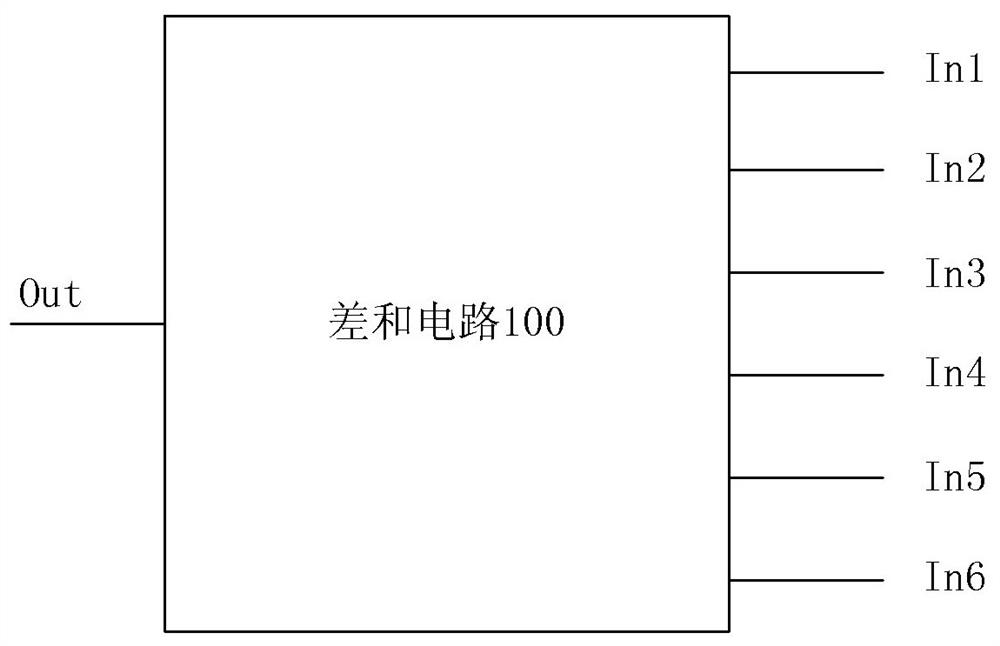
[0010] The difference sum circuit in the lateral logging tool of the present invention calculates the differences of the input signals in pairs and then sums the differences of the signals in pairs. Hereinafter, the differential sum circuit in the lateral logging tool of the present invention will be described in detail according to the accompanying drawings.

[0011] figure 1 is a schematic block diagram of the differential sum circuit in the lateral logging tool of the p...


PUM


Abstract

The invention provides a difference sum circuit in a lateral logger, and the circuit is used for an acquisition circuit on the front end of an acquisition system in a lateral logger. The difference sum circuit in a lateral logger comprises a difference sum output end and N input ends, wherein N is an even number larger than or equal to 2. For N signals respectively input from the N input ends, the difference sum circuit obtains the difference of each two signals, and obtains N / 2 signal differences, and performs summation on the N / 2 signal differences, and outputs the obtained sum from the difference sum output end. The difference sum circuit performs subtraction on each two input signals of the plurality of signals, and then performs summation on the differences of each two signals, so as to reduce error of signal acquisition and improve measuring precision of the front end of the acquisition system.

Description

Technical field: [0001] The invention relates to a difference sum circuit used in the front end of a signal acquisition system in a lateral logging instrument. Background technique [0002] In a lateral logging tool, multiple signals collected by a signal acquisition system need to be calculated. In the past, it was common to sum the collected signals in pairs first and then find the difference of the sum of the signals in pairs. Here, this circuit is referred to as "sum and difference circuit". Due to the reason of the sum and difference circuit itself, there may be relatively large errors in the signal acquisition results, so a processing circuit with higher precision is required. Invention content: [0003] In view of the above-mentioned problems, the purpose of the present invention is to provide a difference sum circuit in a lateral logging tool, which first calculates the difference of the input signals and then sums the differences of the two signals, thereby reduc...

Claims


Application Information

Patent Timeline
Patent Type & Authority Patents(China)
IPC IPC(8): E21B47/00E21B49/00
Inventor 高秀晓白庆杰肖占山张森峰于振南胡海涛姚春明朱瑞明邵琨
Owner CNPC GREATWALL DRILLING ENG
Why Eureka
Try Eureka