Limited stroke ball screw

A ball screw and ball technology, applied in the direction of belt/chain/gear, mechanical equipment, transmission, etc., can solve problems such as mechanism failure, inapplicability, elastic fatigue, etc.

Active Publication Date: 2018-04-17
HIWIN TECH
View PDF4 Cites 0 Cited by
  • Summary
  • Abstract
  • Description
  • Claims
  • Application Information

AI Technical Summary

Problems solved by technology

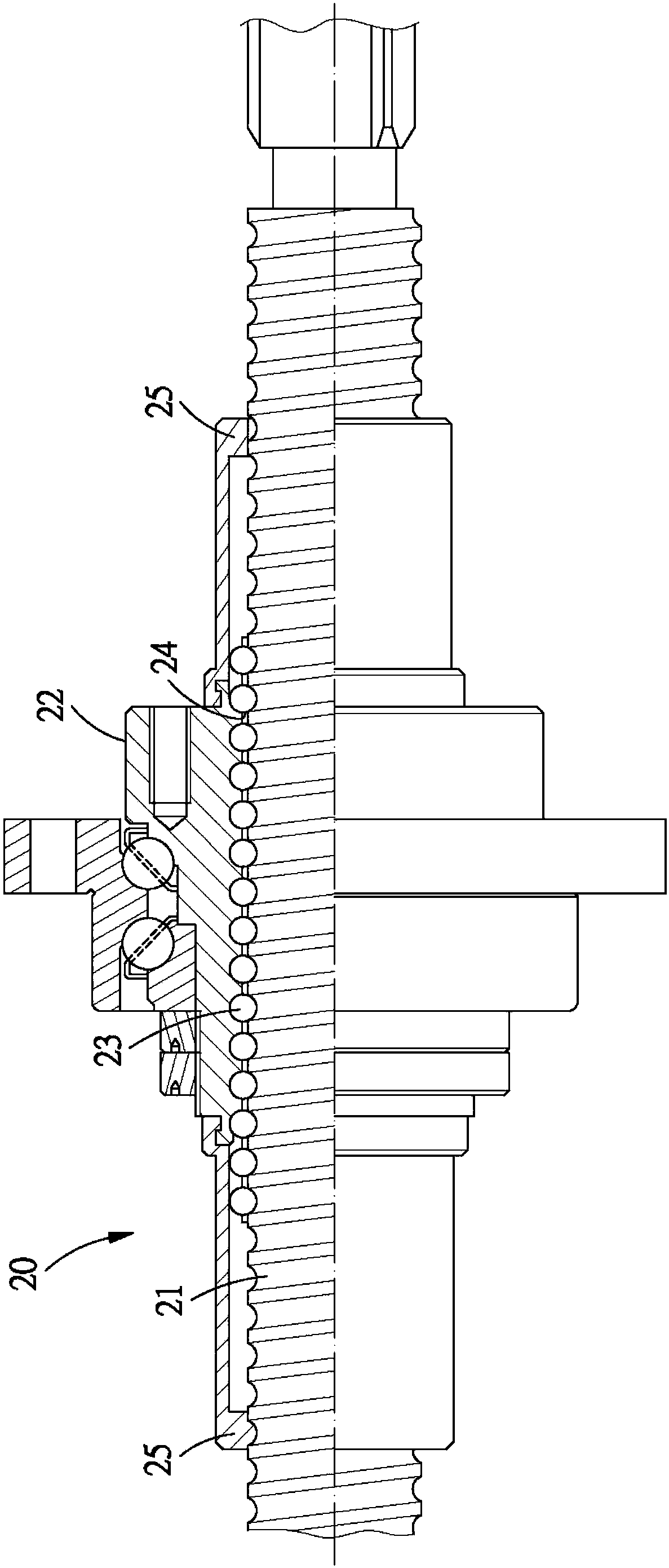
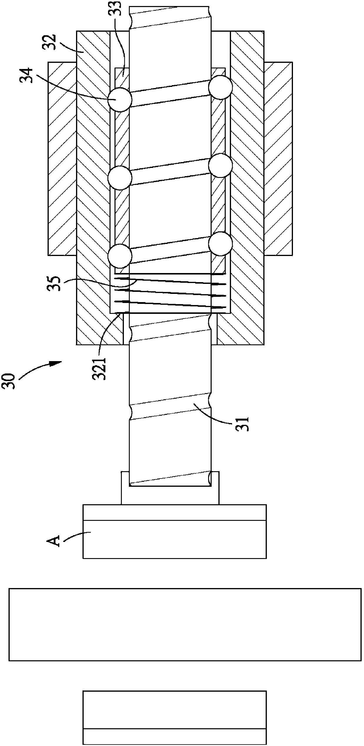
A load direction D2 is defined as the direction in which the screw rod 31 moves in this direction relative to the nut 32 and the load on the screw rod 31 continues to increase to reach the maximum load, that is, image 3 Among them, the direction in which the screw 31 moves to the left relative to the nut 32 and drives the brake block A to brake is the load direction D2, and its reverse is defined as the withdrawal direction D1, and the screw 31 moves to the left relative to the nut 32 to drive the brake. When block A brakes, the ball 34 will bear a maximum load, and at this time, the active force (thrust) of the spring 35 on the ball retaining sleeve 33 is also the largest, and the active force of the spring 35 will limit the displacement of the ball retaining sleeve 33. And the displacement of this ball retaining sleeve 33 is forcibly limited then also can limit the axial displacement between ball 34 and nut 32, has increased the frictional resistance of ball 34, and therefore and figure 2 The disadvantages of the design are the same, which will reduce the mechanical efficiency and output of the overall mechanism
Moreover, with image 3 In the case where the ball screw 30 is used in the brake system, when the screw 31 of the ball screw 30 drives the brake block A to output force, the spring 35 receives the maximum compression force under the condition that the maximum output force of the brake block A is required, and At the same time, it produces the largest reverse elastic force, which directly offsets the output of the overall mechanism. It is simply not applicable in the use situation that requires a large output, which affects the safety of use.
In addition, under the continuous operation of the overall mechanism of the ball screw 30, the spring 35 will produce elastic fatigue and elastic fatigue, which will lead to mechanical failure or unexpected situations such as changing the screw stroke, so the operational stability of the ball screw 30 There is still a lot of room for improvement

Method used


Image

  • Limited stroke ball screw
  • Limited stroke ball screw
  • Limited stroke ball screw

Examples


Embodiment Construction

[0052] In order to enable the examiner to have a further understanding and understanding of the purpose, features and functions of the present invention, please cooperate with [simplified description of drawings] to describe in detail below.

[0053] The preferred embodiment of the limited stroke ball screw of the present invention is as follows: Figures 4 to 12 shown, including:

[0054] A screw 40 extends along an axial direction X, and the outer surface of the screw 40 has an external helical groove 41; and the vertical axis X is defined as a radial direction Y;

[0055] A nut 50 is provided with a set of holes 51 along the axial direction X, and an inner helical groove 511 is provided on the inner surface of the set hole 51, the nut 50 can be slipped on the outside of the screw rod 40 along the axial direction X, and the outer helical A plurality of balls 60 can be accommodated between the groove 41 and the inner helical groove 511; one end of the nut 50 extends inwardly...


PUM


Abstract

The invention discloses a limited-stroke ball screw, which mainly includes a nut threaded on the screw, a plurality of balls arranged between the nut and the screw, and when each ball is displaced toward the exit direction, the displacement speed of each ball relative to the screw in the axial direction Divided by the axial displacement speed of the nut relative to the screw is the exit speed ratio; and when each ball is displaced towards the load direction, the axial displacement speed of each ball relative to the screw divided by the axial displacement speed of the nut relative to the screw is Load speed ratio; at the same time, the exit speed ratio is smaller than the load speed ratio, so that the displacement of each ball towards the exit direction can finally touch the stopper and stop, and when it is displaced towards the load direction, it can disengage from the stopper and move towards the other end without displacement. The frictional resistance is increased by the blocking of the stopper, thereby reducing the displacement resistance of each ball under load; ensuring that the overall device can achieve the purpose of truly stable output; and the overall composition and structure of the present invention is simple, which can reduce production difficulty and improve economic benefits , and increase product reliability.

Description

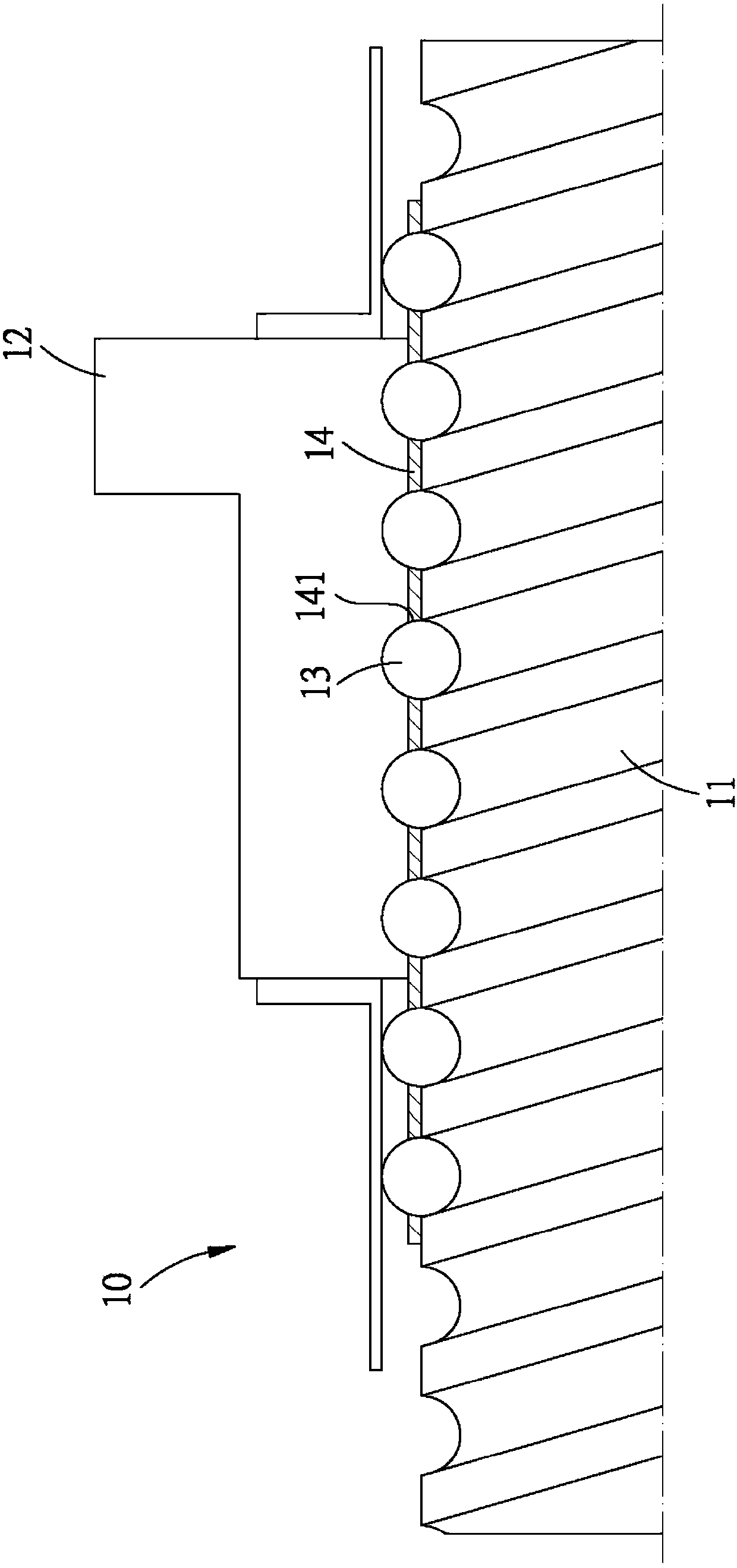
technical field [0001] The invention provides a limited-stroke ball screw, which is related to a linear transmission device. Background technique [0002] The ball screw is an important linear transmission device with high efficiency and high precision transmission characteristics so that it is widely used in various transportation machinery; and the general ball screw mainly consists of a screw outer sleeve and a nut. The spiral groove between the screw and the nut accommodates a plurality of balls in close contact with each other. When the ball screw in this form is in operation, the contact and friction between the balls will generate running resistance. [0003] Therefore, there is another form of ball screw 10 such as figure 1 As shown, it also includes a screw rod 11 and a nut 12, a plurality of balls 13 are arranged between the two, the difference is that a cylindrical ball retaining sleeve 14 is arranged between the screw rod 11 and the nut 12, The peripheral surfa...

Claims


Application Information

Patent Timeline
Patent Type & Authority Patents(China)
IPC IPC(8): F16H25/22
Inventor 郭长信
Owner HIWIN TECH
Why Eureka
Try Eureka