
Redundant padding method for modified chip designs

A filling method and chip design technology, which is applied in computing, special data processing applications, instruments, etc., can solve the problems of many reprinted masks and high costs, and achieve the effect of reducing changes and reducing costs

Active Publication Date: 2019-03-08
SEMICON MFG INT (SHANGHAI) CORP
View PDF4 Cites 0 Cited by
  • Summary
  • Abstract
  • Description
  • Claims
  • Application Information

AI Technical Summary

Problems solved by technology

In the existing scheme, the redundant filling of the modified layer is to abandon the previous redundant filling scheme, and re-fill the redundant filling of all the modified layers, resulting in more masks that need to be reproduced, and the cost is higher

Method used


Image

  • Redundant padding method for modified chip designs
  • Redundant padding method for modified chip designs
  • Redundant padding method for modified chip designs

Examples


Embodiment Construction

[0020] In the following description, numerous specific details are given in order to provide a more thorough understanding of the present invention. It will be apparent, however, to one skilled in the art that the present invention may be practiced without one or more of these details. In other examples, some technical features known in the art are not described in order to avoid confusion with the present invention.

[0021] It should be understood that the invention can be embodied in different forms and should not be construed as limited to the embodiments set forth herein. Rather, these embodiments are provided so that this disclosure will be thorough and complete, and will fully convey the scope of the invention to those skilled in the art.

[0022] The terminology used herein is for the purpose of describing particular embodiments only and is not intended to be limiting of the invention. As used herein, the singular forms "a", "an" and "the / the" are intended to include...


PUM


Abstract

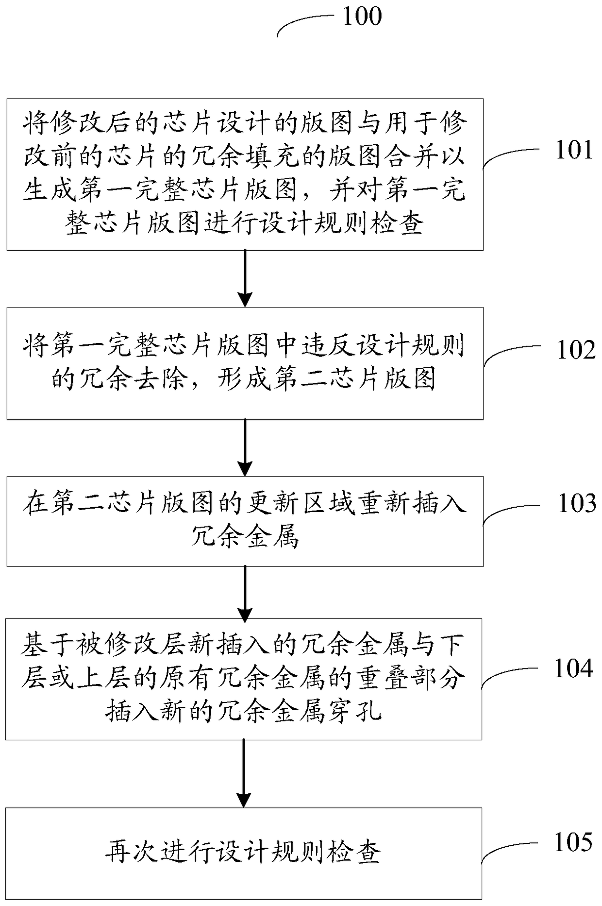
The invention provides a dummy fill method for modified chip design. The dummy fill method comprises: combining the layout of modified chip design with the layout used for dummy fill of a chip before modification, to generate a first complete chip layout, performing design rule checking on the first complete chip layout; removing redundancy which violates design rules in the first complete chip layout, to form a second chip layout; and reinserting redundancy metal in the updating region of the second chip layout. The dummy fill method for modified chip design is based on a previous dummy fill scheme, and can reduce modification of design on original dummy fill, and reduces photomasks which need to reproduce, so as to reduce cost.

Description

technical field [0001] The present invention relates to the field of semiconductor technology, in particular to a dummy fill method for modified chip design. Background technique [0002] In the manufacturing process, chemical mechanical polishing (CMP) is a technique used to achieve wafer planarization. Although CMP has a good planarization effect, due to the non-uniform pattern density of the underlying layout, it will lead to non-uniform changes in the thickness of the dielectric after polishing. Redundant filling is a very widely used CMP planarization enhancement technique. [0003] When modifying the design of one or more layers of metal layers, it is necessary to reproduce the metal / via mask of this layer or layers, and therefore it is also necessary to perform redundant filling on the modified layer again. In the existing solution, the redundant filling of the modified layer is to abandon the previous redundant filling scheme, and re-fill the redundant filling of a...

Claims


Application Information

Patent Timeline
Patent Type & Authority Patents(China)
IPC IPC(8): G06F17/50
Inventor 姜霖
Owner SEMICON MFG INT (SHANGHAI) CORP
Learn More