Portable cable conductor paying off device

A pay-off device and cable wire technology, applied in cable laying equipment and other directions, can solve the problems of hand wear, unsuitable carrying volume and weight pay-off rack, and cables are rolled into a twist shape, etc., to achieve the effect of being easy to carry

Inactive Publication Date: 2016-08-10
GAOTANG COUNTRY POWER SUPPLY BUREAU OF STATE GRID SHANDONG ELECTRIC POWER CO
View PDF0 Cites 3 Cited by
  • Summary
  • Abstract
  • Description
  • Claims
  • Application Information

AI Technical Summary

Problems solved by technology

However, the environment in the actual operation is relatively unsatisfactory, and it is not suitable to carry a pay-off frame with a large volume and weight. Therefore, construction workers often directly pull the cable by hand, so that one end of the cable is pulled from

Method used


Image

  • Portable cable conductor paying off device
  • Portable cable conductor paying off device

Examples


Example Embodiment

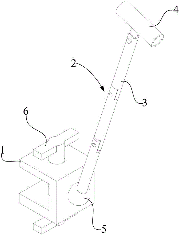
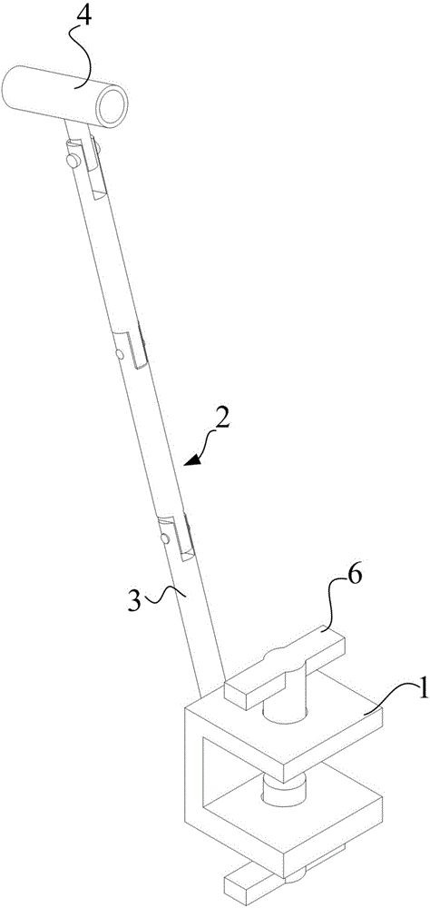
[0018] Example 1, such as figure 1 , figure 2 As shown, this embodiment provides a portable cable pay-off device, which includes a fixing base 1 for fixing the entire device and a guide rod 2 movably connected to the fixing base 1. The fixing base 1 is mainly used to fix the cable roll When multiple devices need to be fixed according to the length of the wire drawn on the bracket and during the wire drawing process, it is convenient to fix to other places. The guide rod 2 is provided with a guide tube 3 at the end of the guide rod 2 away from the fixing base 1. The main function of the guide rod 2 It is matched with the guide tube 3. In this embodiment, the guide tube 3 is a round tube. A connecting rod (not marked in the figure) is provided on the side wall of the guide tube 3, and the connecting rod and the guide tube 3 are arranged vertically. In order to facilitate folding, the guide rod 2 includes at least three adjacent struts 4 pivoted together. In this embodiment, thre...


PUM


Abstract

The invention belongs to the field of electric power auxiliary equipment and relates to cables, in particular to a portable cable pay-off device. It includes a fixing base for fixing the whole device and a guide rod movably connected with the fixing base. The end of the guide rod away from the fixing base is provided with a guide cylinder. The guide rod includes at least three adjacent sections pivotally connected together. rod, and the guide cylinder is pivotally connected with the guide rod. Compared with the prior art, the advantages and positive effects of the present invention are that, by providing a portable cable pay-off device, the present invention uses the guide cylinder to guide the cable regularly from the coil, so that it does not Rolling occurs, and at the same time, the structure of the device provided by the invention is a foldable structure, which is easy to carry and can be applied to various complex environments.

Description

technical field [0001] The invention belongs to the field of electric power auxiliary equipment and relates to cables, in particular to a portable cable pay-off device. Background technique [0002] Cables are the main carrier of electric energy transmission, and the usage and laying work are huge. At present, when laying cables in the power system, there are mainly two methods. One is to use a crane to lay out the wires. If a crane is used to lay out the wires, the limitations of the construction site must be considered. Work is difficult. The other is to rely on the cable pay-off frame, place the cable reel on the rotatable pay-off frame and pull the cable by hand to realize the release. The cable frame is generally large in size and very inconvenient to carry, and the cable frame needs to be placed On a flat bottom surface, otherwise the cable rack may roll over when the cable is pulled. However, the environment in the actual operation is relatively unsatisfactory, and...

Claims


Application Information

Patent Timeline
IPC IPC(8): H02G1/06
CPCH02G1/06
Inventor 毛广强刘建忠张敏赵金洋卢生李玉梅潘盼徐霞王厚友
Owner GAOTANG COUNTRY POWER SUPPLY BUREAU OF STATE GRID SHANDONG ELECTRIC POWER CO
Why Eureka
Try Eureka