Charging control method, terminal, and charger
A charging control method and charger technology, which are applied to current collectors, battery circuit devices, electric vehicles, etc., can solve problems such as potential safety hazards, and achieve the effect of avoiding damage
- Summary
- Abstract
- Description
- Claims
- Application Information
AI Technical Summary
Problems solved by technology
Method used
Image

Examples
Embodiment 1
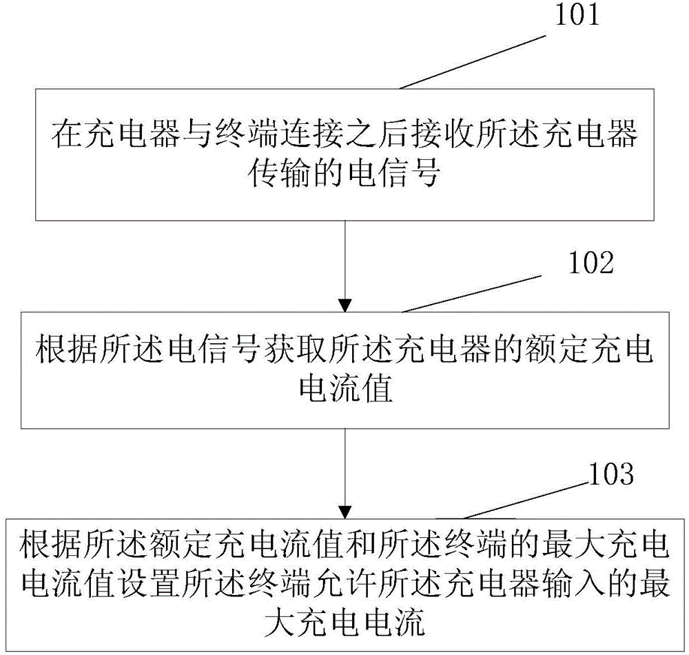
[0056] Considering that there are potential safety hazards for users when charging with non-standard chargers, if the output current of the charger is higher than the maximum design input current of the mobile terminal, and the mobile terminal has no relevant restrictions, then the mobile terminal may be overcharged and damaged; if The output current of the charger is lower than the maximum design input current of the mobile terminal. The charger may work for a long time in a state exceeding the rated power, which will eventually lead to charging damage or even a fire. This embodiment provides a charging control method, which is applied to terminals, such as figure 1 shown, including the following steps:
[0057] Step 101: Receive an electrical signal transmitted by the charger after the charger is connected to the terminal.
[0058]Since different chargers have different rated charging currents, in order to let the terminal know the rated charging current value of the curren...
Embodiment 2
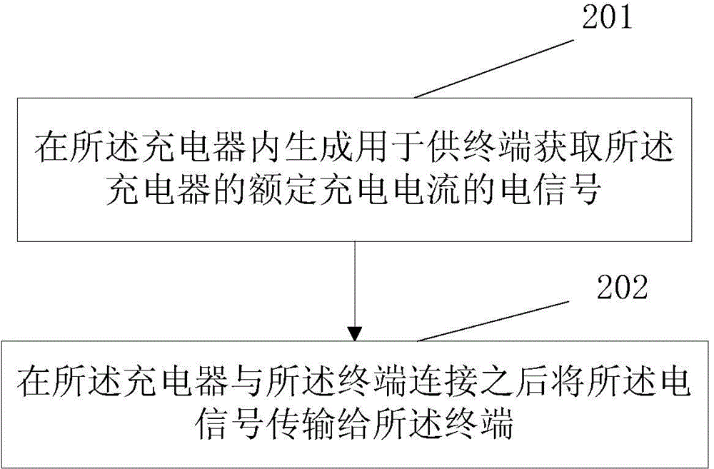
[0079] This embodiment provides a charging control method, which is applied to the charger side, such as figure 2 shown, including the following steps:
[0080] Step 201: Generate an electrical signal in the charger for the terminal to obtain the rated charging current of the charger.
[0081] Since different chargers have different rated charging currents, in order to allow the terminal to know the rated charging current value of the current charger, this embodiment can generate a battery on the charger side for the terminal to obtain the rated charging current of the charger. signal, so that the terminal can obtain the rated charging current value of the current charging according to the bias voltage.
[0082] Preferably, this step specifically includes: generating in the charger a bias voltage signal corresponding to the rated charging current of the charger.
[0083] Specifically, a circuit for defining the rated charging current may be provided in the charger, and the ...
Embodiment 3
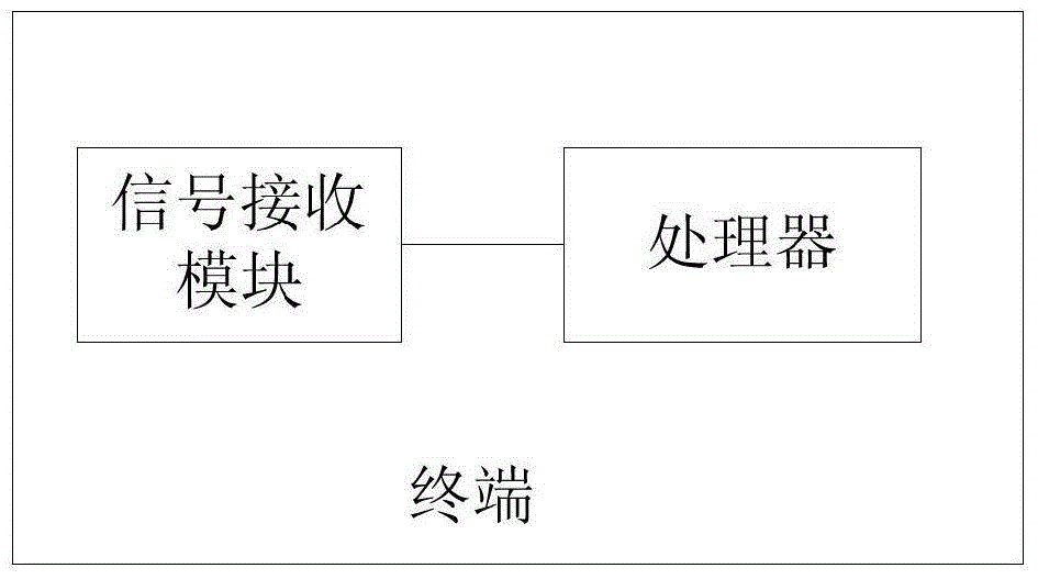
[0089] Such as image 3 As shown, this embodiment provides a terminal, including: a signal receiving module and a processor;
[0090] The signal receiving module is configured to receive the electrical signal transmitted by the charger after being connected to the charger;
[0091] said processor for:
[0092] Acquiring the rated charging current value of the charger according to the electrical signal;
[0093] Setting the maximum charging current that the terminal allows the charger to input according to the rated charging current value and the maximum charging current value of the terminal.
[0094] Preferably, the signal receiving module in this embodiment can be a charging interface of the terminal. After the charging interface is connected to the charging plug of the charger, it receives the electrical signal transmitted by the charging plug, and then transmits it to the processor.
[0095] Preferably, the electrical signal in this embodiment may include a bias voltage...
PUM
 Abstract
Description
Claims
Application Information
 - R&D
- Intellectual Property
- Life Sciences
- Materials
- Tech Scout
- Unparalleled Data Quality
- Higher Quality Content
- 60% Fewer Hallucinations
Browse by: Latest US Patents, China's latest patents, Technical Efficacy Thesaurus, Application Domain, Technology Topic, Popular Technical Reports.
© 2025 PatSnap. All rights reserved.Legal|Privacy policy|Modern Slavery Act Transparency Statement|Sitemap|About US| Contact US: help@patsnap.com