Emergency bypass device of porous ceramic dust remover

A technology of porous ceramics and emergency bypass, applied in membrane filters, transportation and packaging, chemical instruments and methods, etc., can solve problems such as porous ceramics clogging system operation, achieve flexible treatment, recycling, and prevent air leakage Effect

Active Publication Date: 2016-08-17
HUNAN CHANGZHONG MACHINERY
View PDF5 Cites 0 Cited by
  • Summary
  • Abstract
  • Description
  • Claims
  • Application Information

AI Technical Summary

Problems solved by technology

[0004] In order to solve the technical problem that the possible clogging of porous ceramics during operation affects the operation of the system in the prior art, the present invention aims to provide an emergency bypass device for porous ceramic dust collectors to provide a new dust removal channel

Method used


Image

  • Emergency bypass device of porous ceramic dust remover
  • Emergency bypass device of porous ceramic dust remover

Examples


Embodiment 1

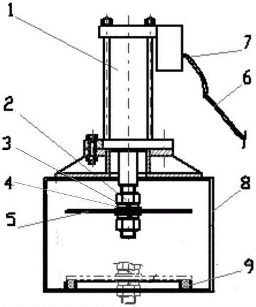
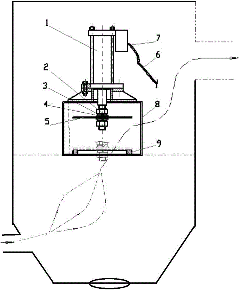
[0015] Example 1: The emergency bypass device of the porous ceramic dust collector is installed inside the porous ceramic dust collector, specifically on the flower plate between the upper box and the lower box, and a circular bypass hole is opened in the middle of the flower plate. The device includes a valved cylinder (1) equipped with a solenoid valve, and a valve plate (5) is arranged at the bottom of the cylinder; the valve plate (5) is fixed by a nut (2), a flat washer (3), and a spring washer (4). Air intake pipe (6) and copper gas nozzle (7) are arranged. The valved cylinder is installed on the base (8), and there are air holes on both sides of the base (8), and a circular graphite gasket (9) for sealing is arranged around the bypass hole of the partition. The valve plate (5) moves up and down through the expansion and contraction of the valved cylinder (1). When the valve plate (5) stretches and moves downward, it can fit closely with the graphite pad installed on the...

Embodiment 2

[0016] Example 2: The emergency bypass device of the porous ceramic dust collector is installed inside the porous ceramic dust collector, specifically on the flower plate between the upper box and the lower box, and a circular bypass hole is opened in the middle of the flower plate. The device includes a valved cylinder (1) equipped with a solenoid valve, and a valve plate (5) is arranged at the bottom of the cylinder; the valve plate (5) is fixed by a nut (2), a flat washer (3), and a spring washer (4). Air intake pipe (6) and copper gas nozzle (7) are arranged. The valved cylinder is installed on the base (8), and there are air holes on both sides of the base (8), and a circular graphite gasket (9) for sealing is arranged around the bypass hole of the partition. The valve plate (5) moves up and down through the expansion and contraction of the valved cylinder (1). When the valve plate (5) stretches and moves downward, it can fit closely with the graphite pad installed on the...


PUM


Abstract

The invention provides an emergency bypass device of a porous ceramic dust remover. The emergency bypass device is arranged inside the porous ceramic dust remover, a bypass system is mounted on a tube nest between an upper box body and a lower box body of the dust remover, a round bypass hole is formed in the middle of the tube net, the device comprises a valved cylinder equipped with an electromagnetic valve, a valve plate is arranged at the bottom of the cylinder and is fixed through a nut, a flat gasket and an elastic gasket, and the top of the cylinder is equipped with an air inlet pipe and a copper air nozzle. The valved cylinder is mounted on a base, air holes are formed in two sides of the base, and a round graphite gasket used for sealing is arranged at the periphery of a partition bypass hole. The emergency bypass device has the characteristics that the structure is simple and reasonable, the stress is uniform, the installation is easy and the cost is low.

Description

technical field [0001] The invention relates to a flue gas dedusting device, in particular to an emergency bypass device for a porous ceramic dust collector. Background technique [0002] Porous ceramic dust collector has outstanding advantages such as high temperature resistance, corrosion resistance, cleaning resistance, high mechanical strength, stable structure without deformation and long life, so it is considered to be the best choice for hot particle filter materials. The porous ceramic dust collector has high separation efficiency, and the dust removal rate can generally exceed 99.99%. Its filtration performance, especially for fine particle filtration below PM2.5, is unmatched by other dust removal and dust collection equipment. In addition, the microporous ceramic filter membrane will not produce secondary pollution, and is the most suitable and promising method for various waste gas treatment. [0003] However, because the sintering flue gas in many industries ha...

Claims


Application Information

Patent Timeline
Patent Type & Authority Applications(China)
IPC IPC(8): B01D46/00B01D46/44B01D46/54
CPCB01D46/0087B01D46/44B01D46/543B01D2275/40B01D46/762B01D46/76
Inventor 文向前吴海燕曾文凤
Owner HUNAN CHANGZHONG MACHINERY
Why Eureka
Try Eureka